Fuel tanks made of “black” iron on any 1970s-1980s era boat are always an issue. Some seem to last forever without a problem; others develop leaks along the welded seams; most eventually leak – it’s just a matter of time.
Sanderling was built in 1987 by Blue Water Yachts in Taiwan, a builder with a good reputation which built a number of DeFever designed trawlers. The craftsmanship is superb and the construction is as substantial as you could find in any boat. She weighs a hefty 18 tons – heavy for a boat that’s about 36 feet on the waterline and about 41 feet overall. The two fuel tanks of 200 gallons each are built of “black iron” (steel) with welded seams, covered with fiberglass on the sides and bottom (not the top). The tanks are located outboard of the engine room behind a bulkhead with sound deadening material attached; an extension of the saloon deck with supporting beams is about six inches above the top of the tanks. The exterior deck is approximately 16-18 inches above the saloon deck.
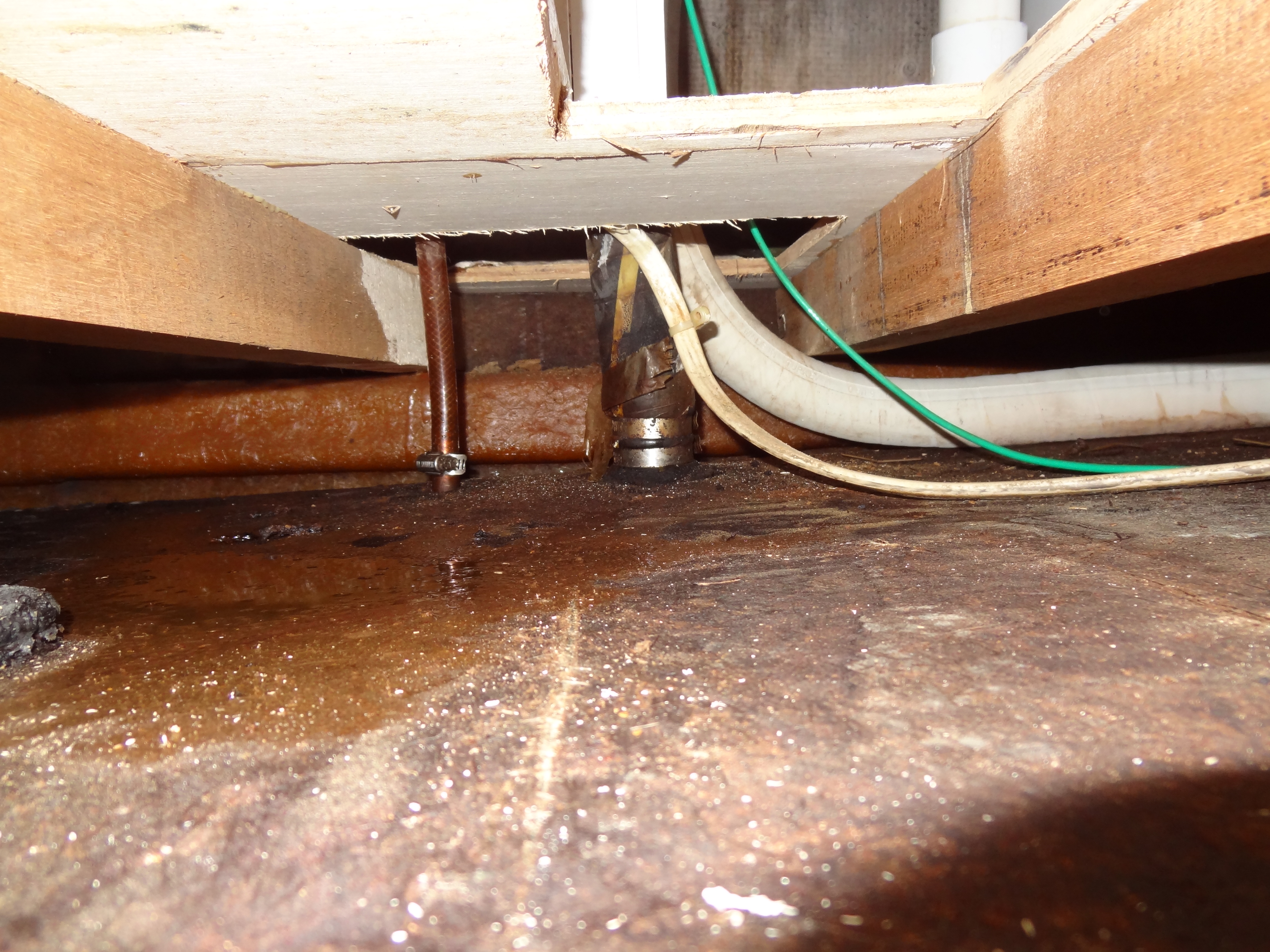
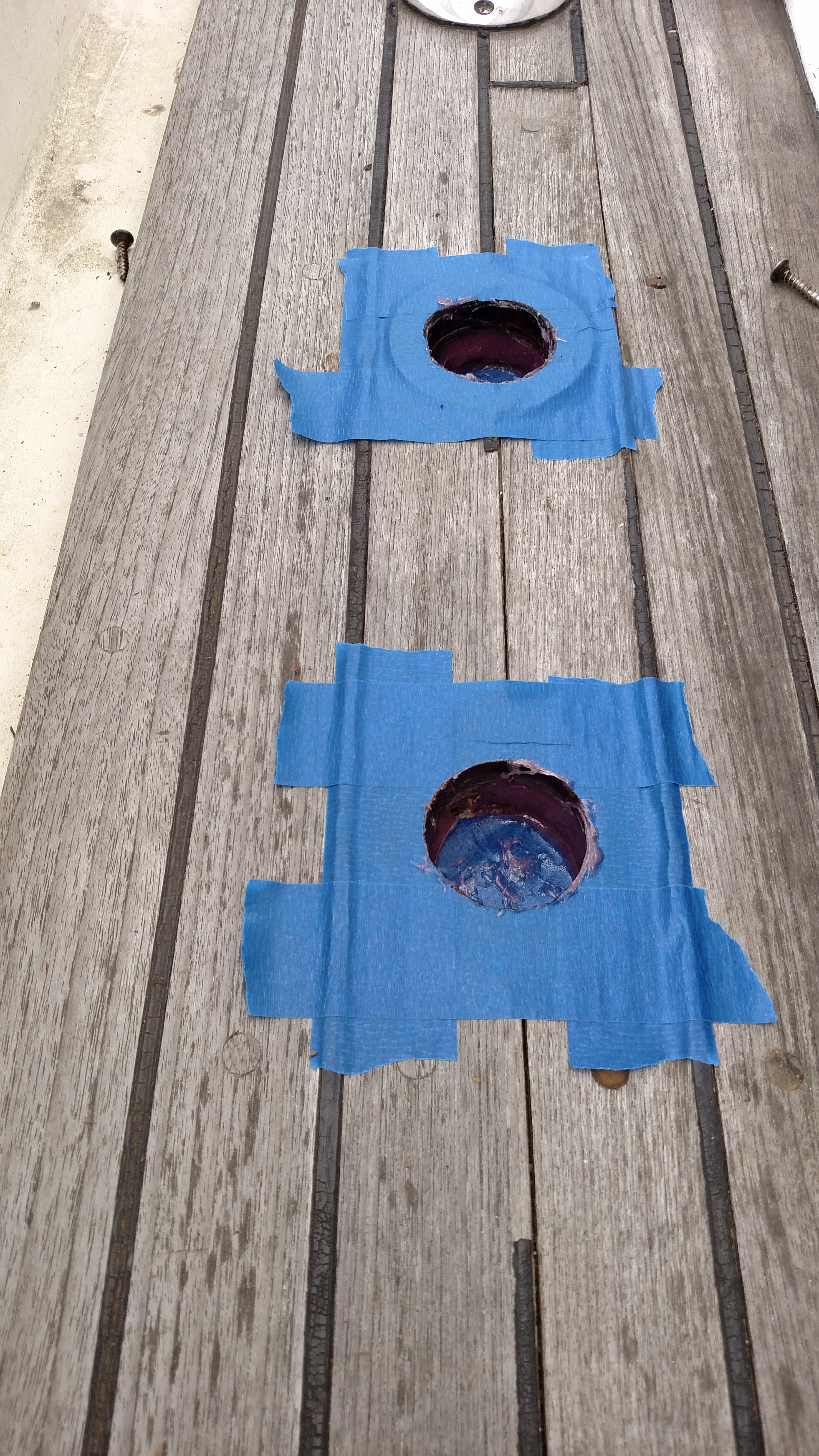
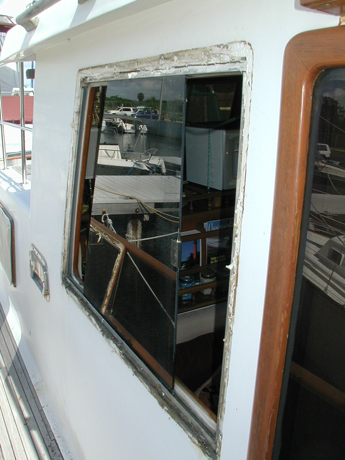
When we purchased Sanderling in 2007 there was no evidence of leaking fuel, either by inspecting the area around the tanks or by the “smell” test. That changed, slightly, over the past two years: whenever we’d fill the tanks with diesel fuel we would observe a little fuel in the side bilge under the starboard fuel tank. If we were in rough seas with full tanks, we’d get the same type of puddling. Eventually that small amount of fuel would find its way into the bilge sump. Once we had been underway for a short time or returned to smoother seas where the fuel wasn’t agitated within the tank, the fuel puddling ceased. We deployed hydrocarbon absorbent pads to absorb the fuel that escaped the tank. It was obvious that the small amounts of fuel was escaping from near the top of the tank. Observation of the tank area around the fuel fill and air vent area showed signs of rust, probably from water seeping through the area of the fuel fill deck fitting. The area around the hose fittings was the only area of the tank that was observable, through a relatively small access hole cut through the deck just above the fuel tank in that location.
We agreed that it was time to replace the fuel tanks as a preventive measure. We have been to this dance before – our former trawler had leaking fuel tanks that we replaced with welded aluminum tanks in 2006 – so we had a rough idea of what was involved in the process and the amount of work that would be involved; we wanted someone with experience in replacing tanks in similar boats, not just someone who thought they could do it. Unfortunately, the boat yard that did that work was no longer in business. After talking with several boat yards in the Melbourne and Port Canaveral area, we were happy to find a yard that had the experience and a knowledgeable crew – Canaveral Custom Boats, also doing business as Delta Boats at Port Canaveral, Florida, and owned by Mark Smith. Interestingly, Canaveral Custom Boats has been in business for a number of years and is actually building 36 and 38 foot sports fishing boats some to Coast Guard certification standards used by commercial “head” boat operators and some smaller boats. Other yards would haul and block Sanderling, but I would be on my own for getting a crew together to replace the tanks – something I did not want to do. Other yards had never replaced fuel tanks but thought their crews were up to the task – again, no thanks!
Mark accompanied me to look at Sanderling’s fuel tanks before giving us an estimate for the cost of the project. We concluded that the boat was built around the tanks during the construction process, and the tanks were too large (36″deep x 42″ high by 60″ long) to fit through the opening into the engine room through the saloon deck (27″ wide), and way too large to fit through the largest saloon door on the boat’s port side (24″ wide). We discussed various options including cutting a larger opening in the saloon’s finished holy and teak flooring (in essence creating another deck hatch running parallel with the current three hatches), and cutting the tanks into removable pieces in the engine room. All options involved removing the engine and possibly the transmission, removing at least a portion of the bulkheads separating the engine room from the fuel tanks, and replacing the tanks with smaller tanksl. In the long run, we settled on cutting the tanks into pieces for removal and building two new tanks to replace the existing single tank on each side.
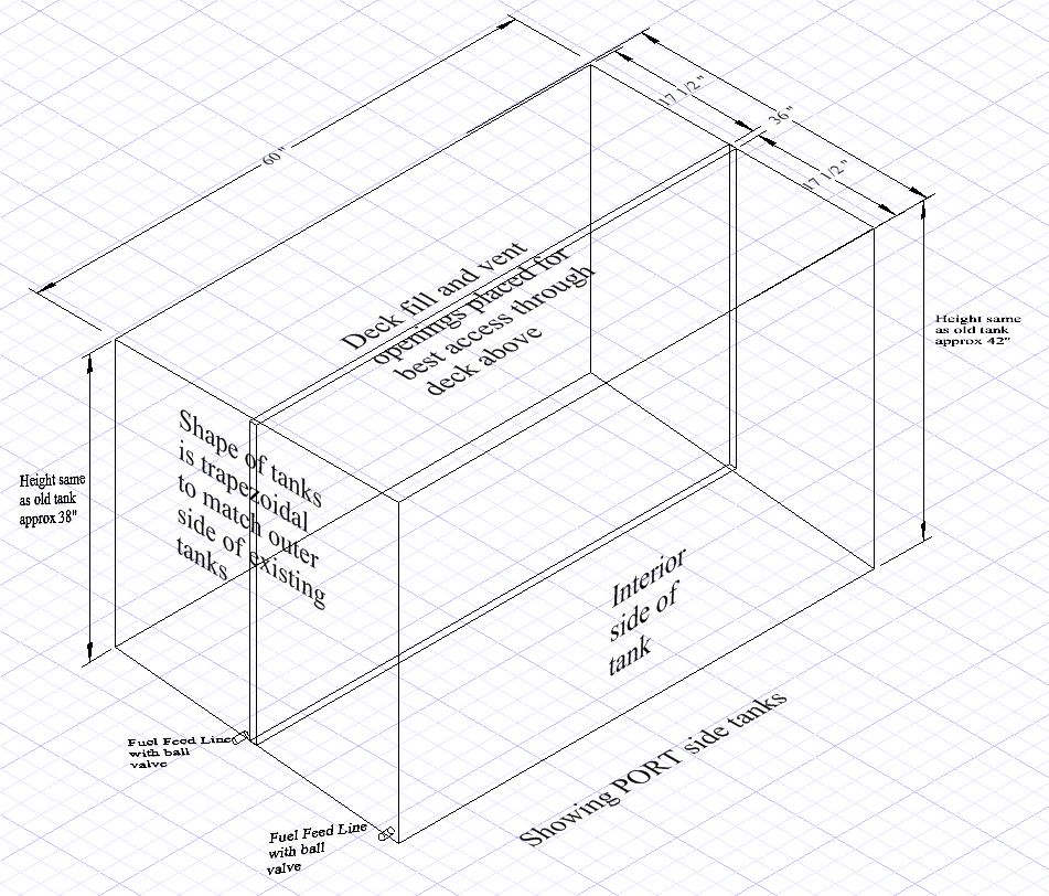
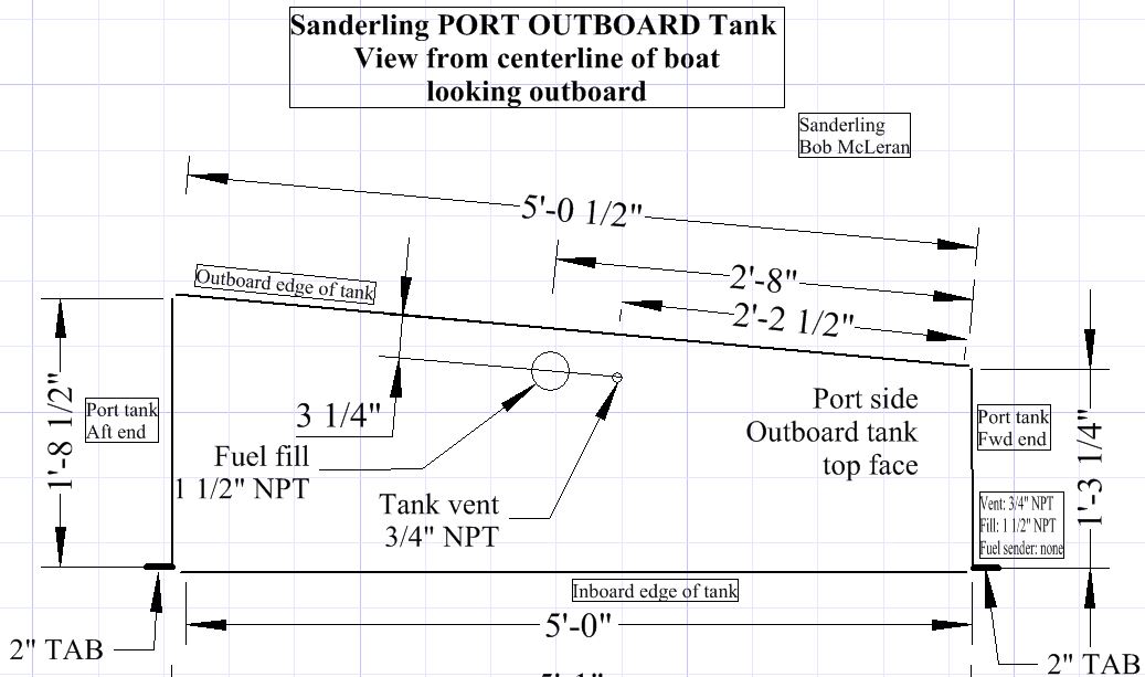
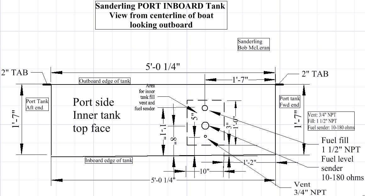
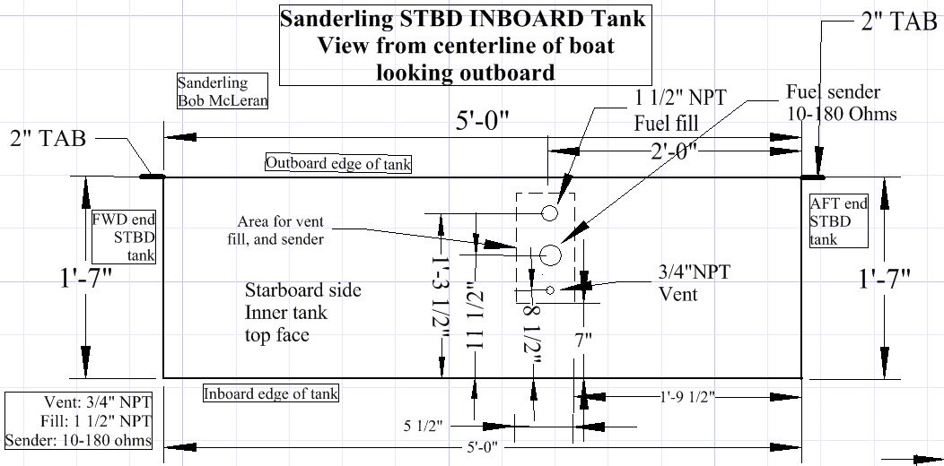
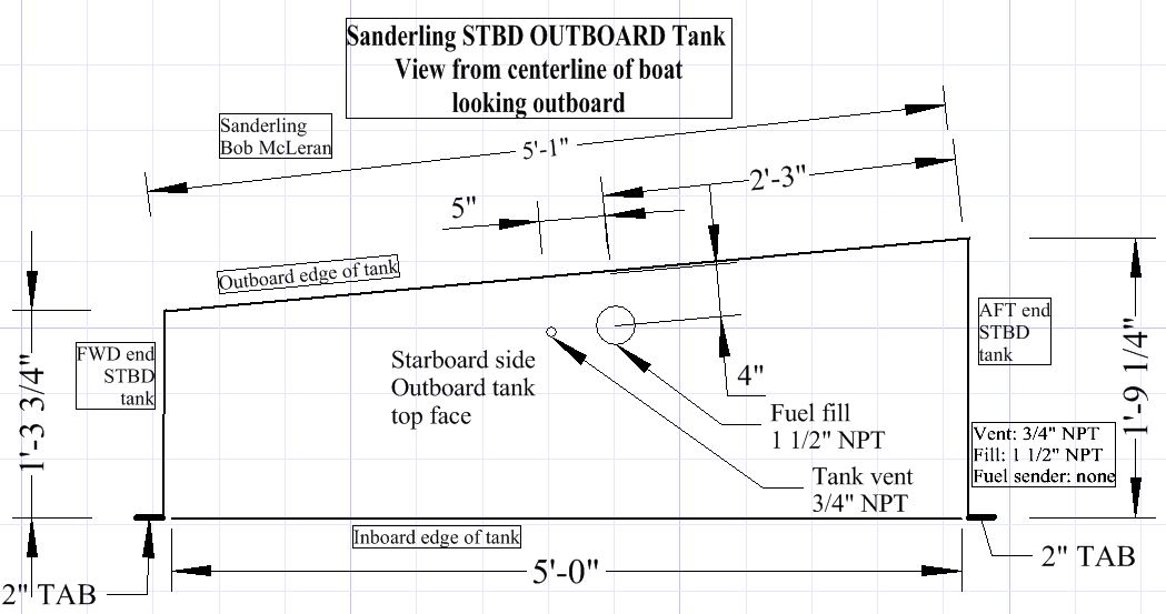
The issue became whether to replace the existing single tanks (one on each side of the engine room) with tanks situated fore and aft of each other (maximum width 24″ fore-aft), or with two long tanks situated side by side (maximum width 60″ fore-aft and max depth 24″ inside-outside). I did a little 3D modelling to get a better idea of how to design the replacement tanks. To get approximately the same fuel capacity in multiple tanks rather than a single tank (200 gallons each side), the latter provided the best solution – fabricate two long and narrow tanks running 60″ lengthwise set side by side with an air space between them to prevent moisture build-up. Each tank will be approximately 18″ deep and will easily fit through the saloon door and through the existing engine room hatch opening. The tanks will be fabricated at Sunshine Welding at Port Canaveral; they have a superb reputation for all sorts of metal fabrications, including fuel tanks; they made the replacement tanks for our previous trawler in 2006.
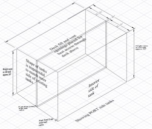
3D drawing approximating new double fuel tanks (PORT side)
The process involves six stages:
- Remove the engine
- Remove the bulkheads
- Remove the tanks
- Install tanks
- Install bulk heads
- Install engine
There are a lot of sub-tasks in the complete work breakdown structure, but this gives a general idea.
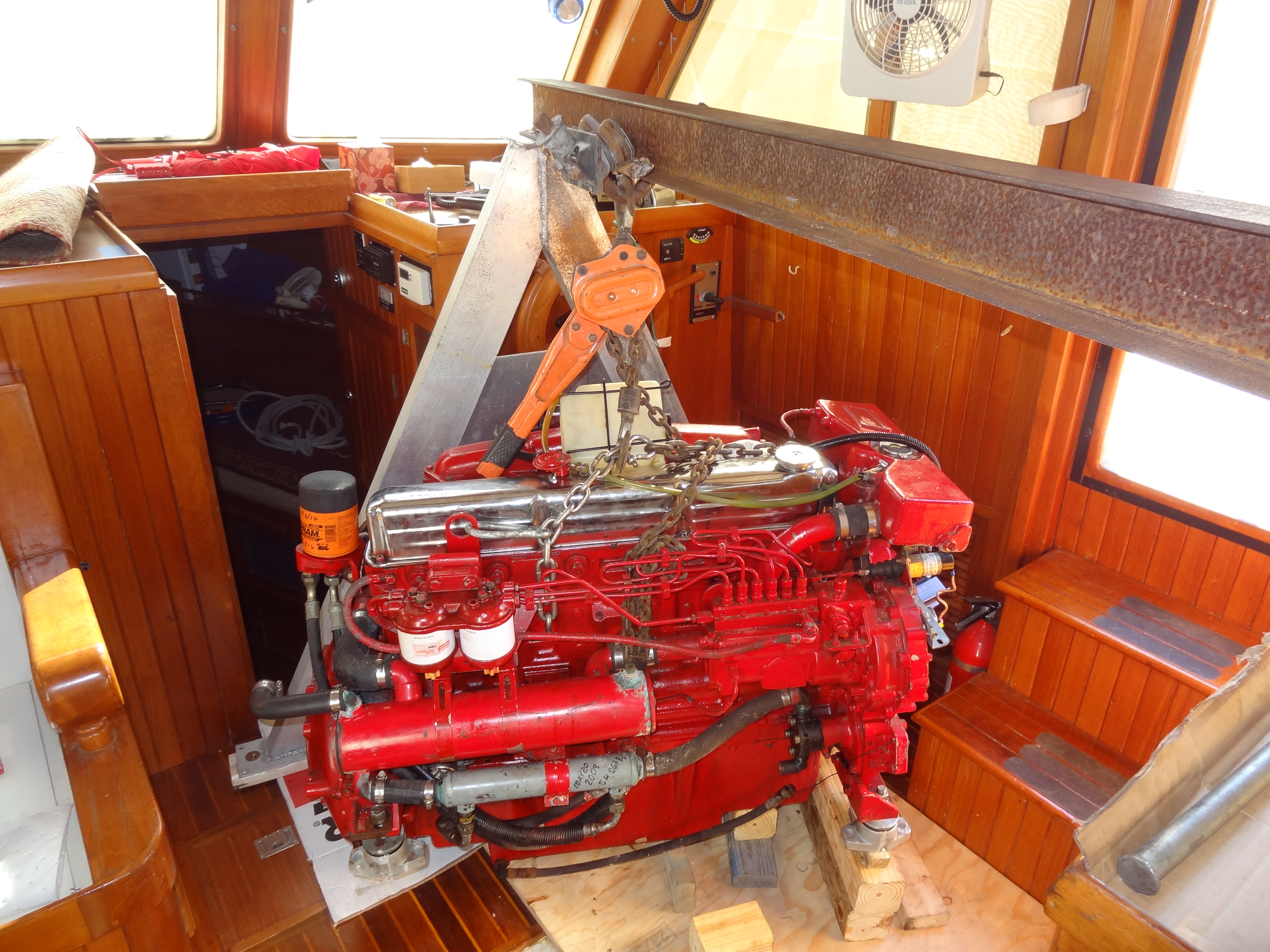
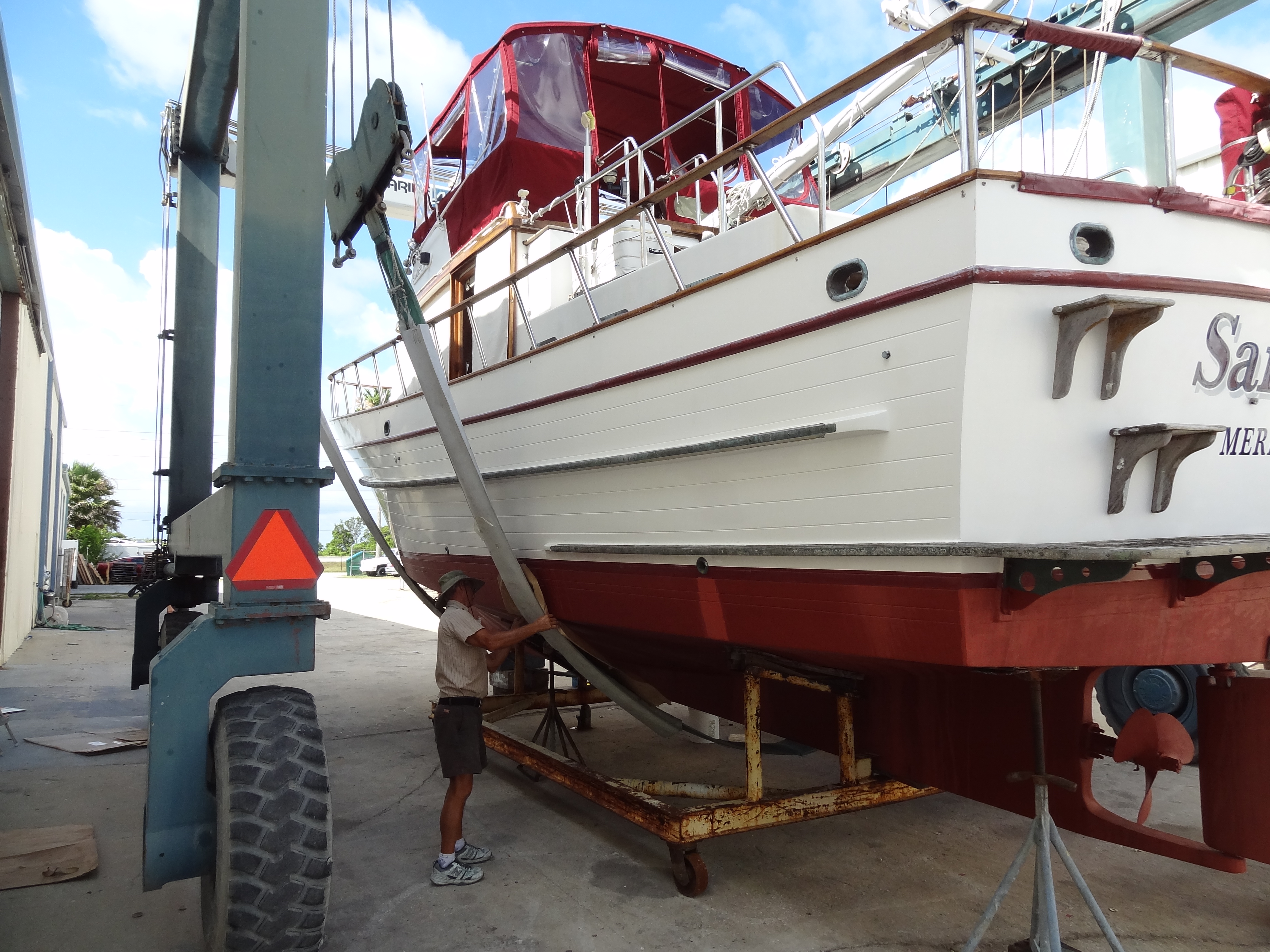
Sanderling was hauled at Cape Marina on February 9th, 2015, power washed, and transported by travel lift to Mark’s yard at Canaveral Custom Boats/Delta Boats where it was transferred to a substantial wheeled dolly. Within three days the Ford-Lehman 135 engine had been removed from the engine room using an I-beam on a steel A-frame with trolley and two chain falls, and was resting on it’s blocked engine mounts on the forward area of the saloon deck. A 4X4 post was set under the saloon deck to provide additional support for the nearly 800 pound engine.
Photos to the point of removing the engine
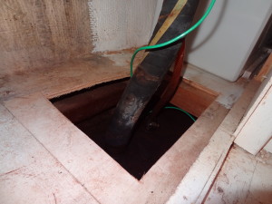
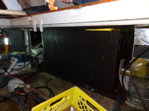
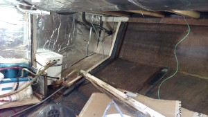
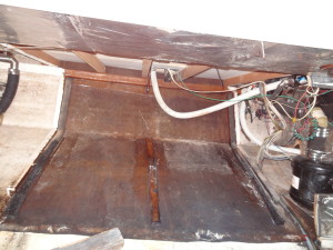
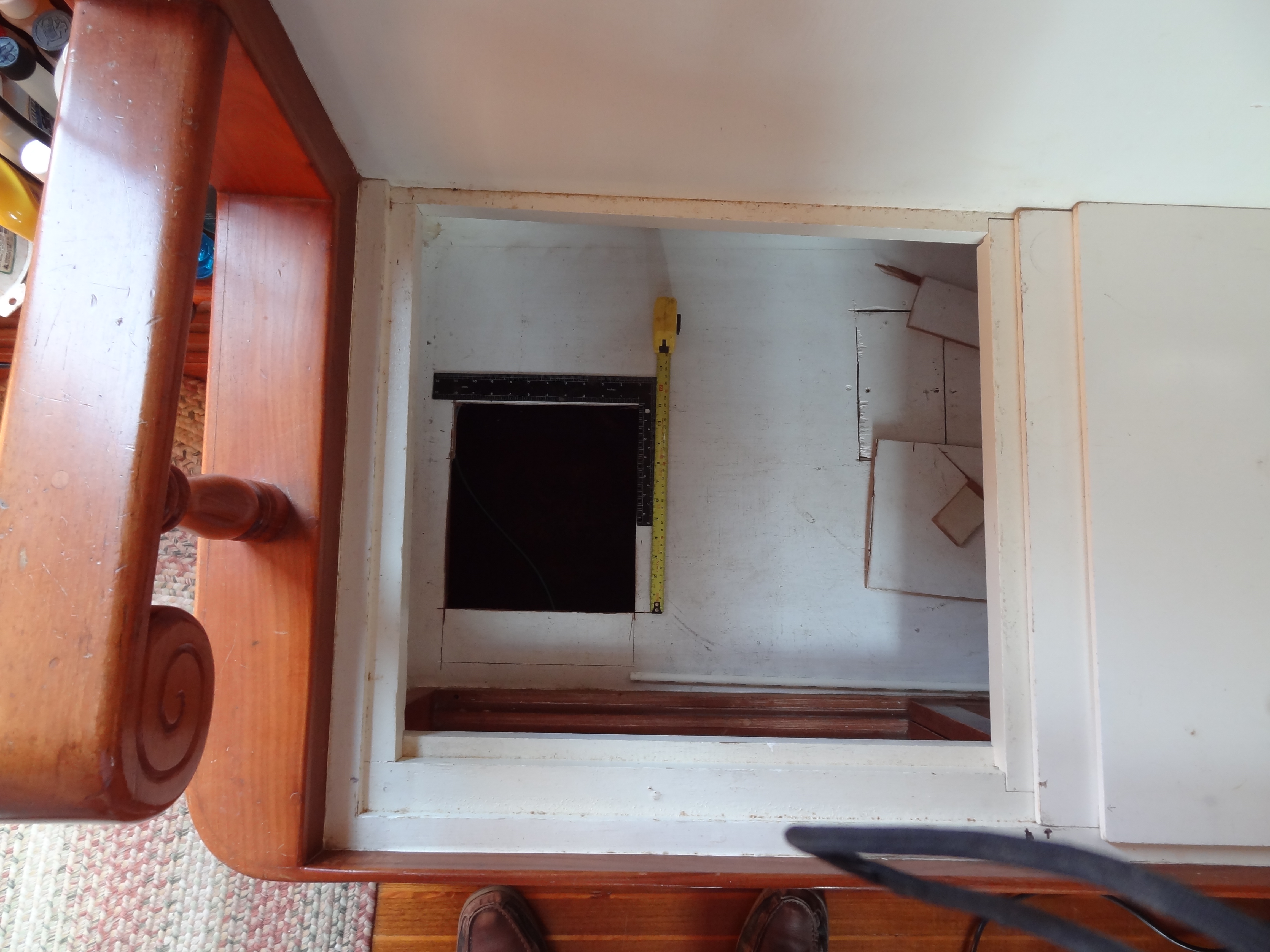
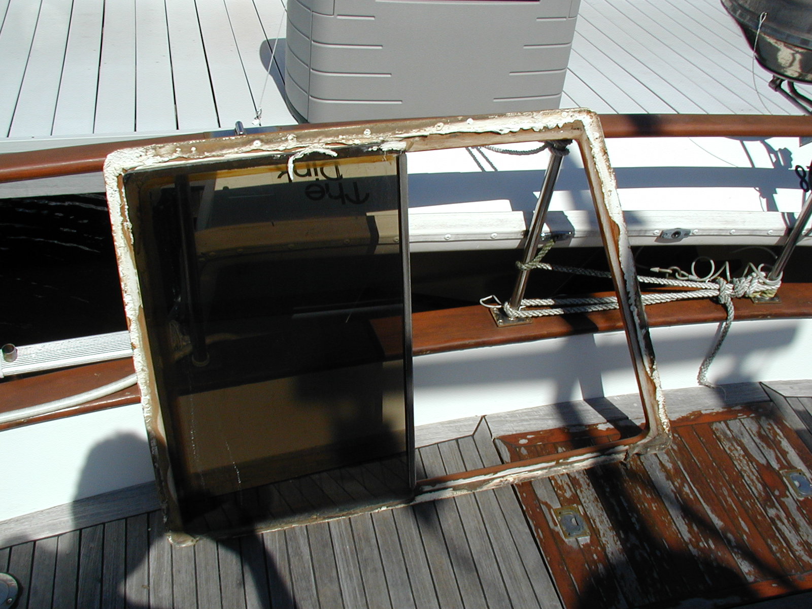
Port side access to fuel tank cut out to provide more access with port holding tank in background – accessed from under stair/ladder from saloon to outer deck

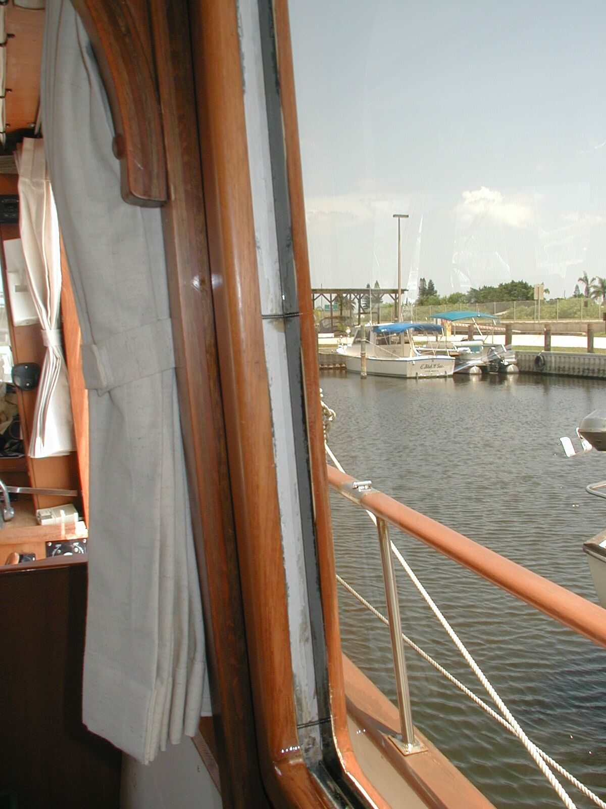
Port side showing space on top of fuel tank with fill hose in background and green fill port grounding wire and starboard holding tank
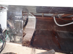
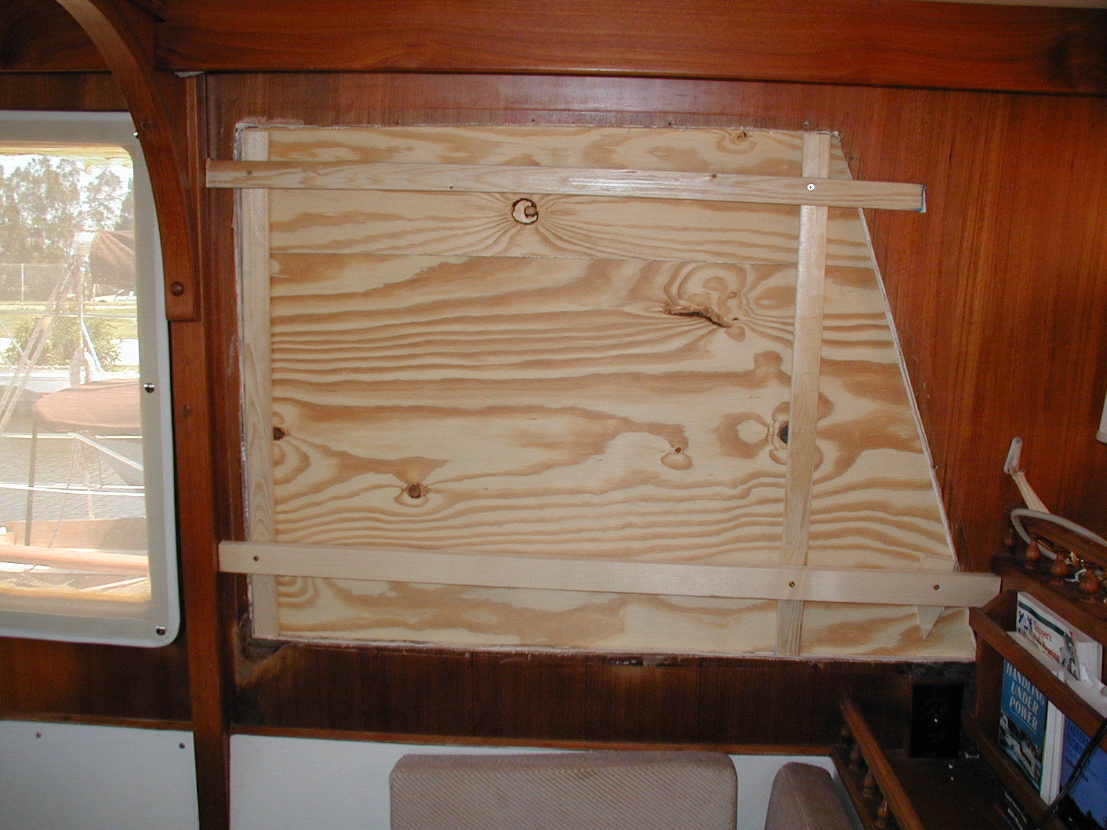
Starboard fuel tank access in background with new access area in foreground – access under sink cabinet – closest cutout is for location of vent and fuel fill on new inboard tank before painting tank surface below cutout with Aluthane aluminum filled urethane metalic coating from Epoxyproducts.com to mark area for tank fabricator
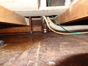
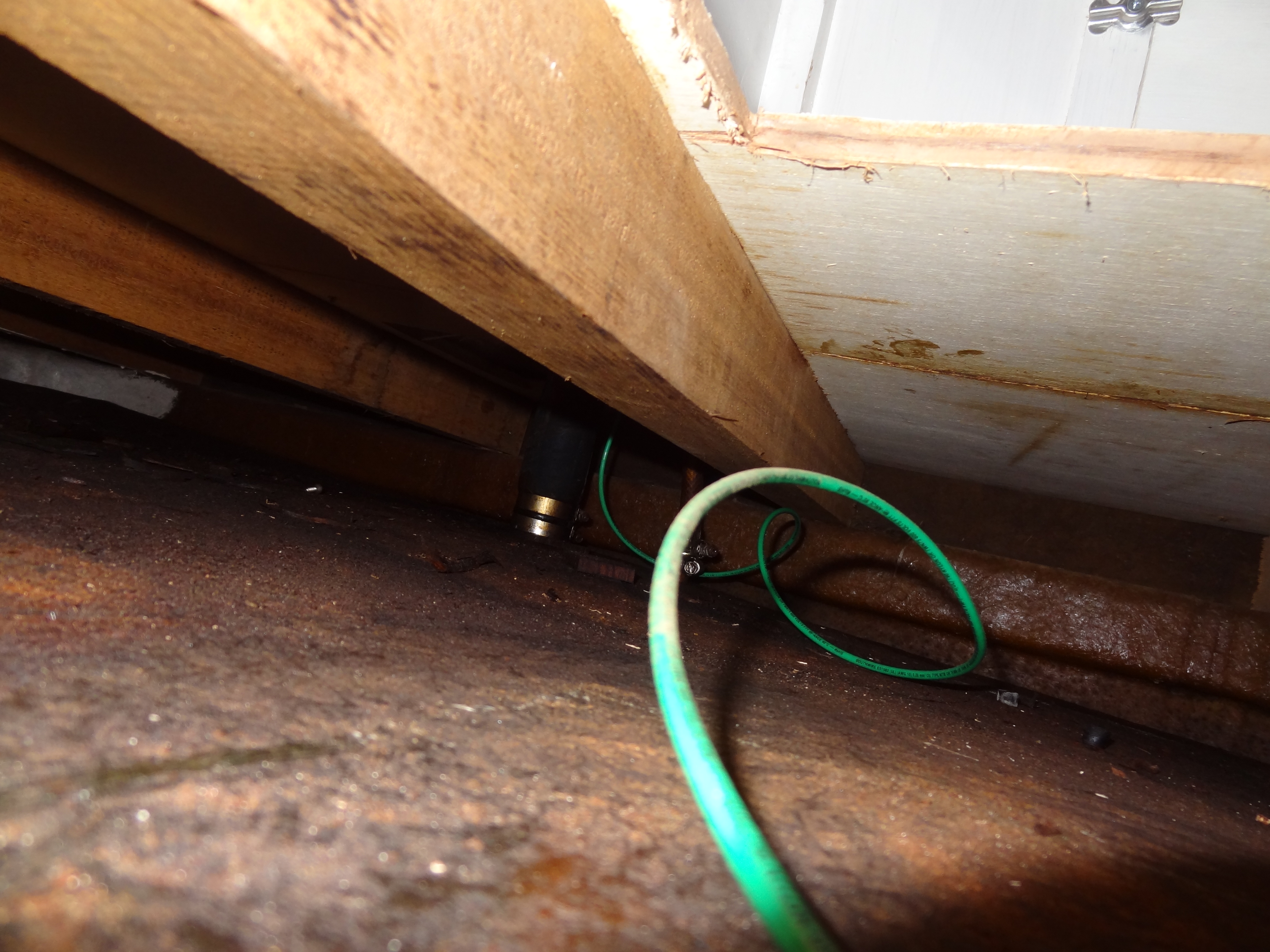
Starboard area between top of tank and saloon deck with supporting beams showing fuel fill and air vent with green deck fill ground wire and sanitation hose from holding tank
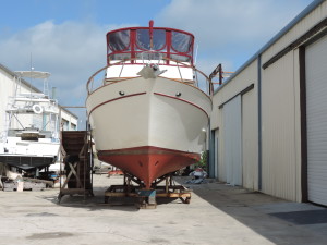
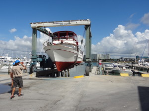
Sanderling at Canaveral Custom Boats (Delta Boats) ready for work
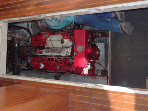
Engine sitting in engine room ready to be lifted
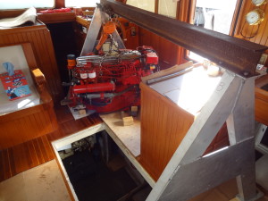
Engine and I-beam on A-frame

Engine sitting on engine mounts with blocks under

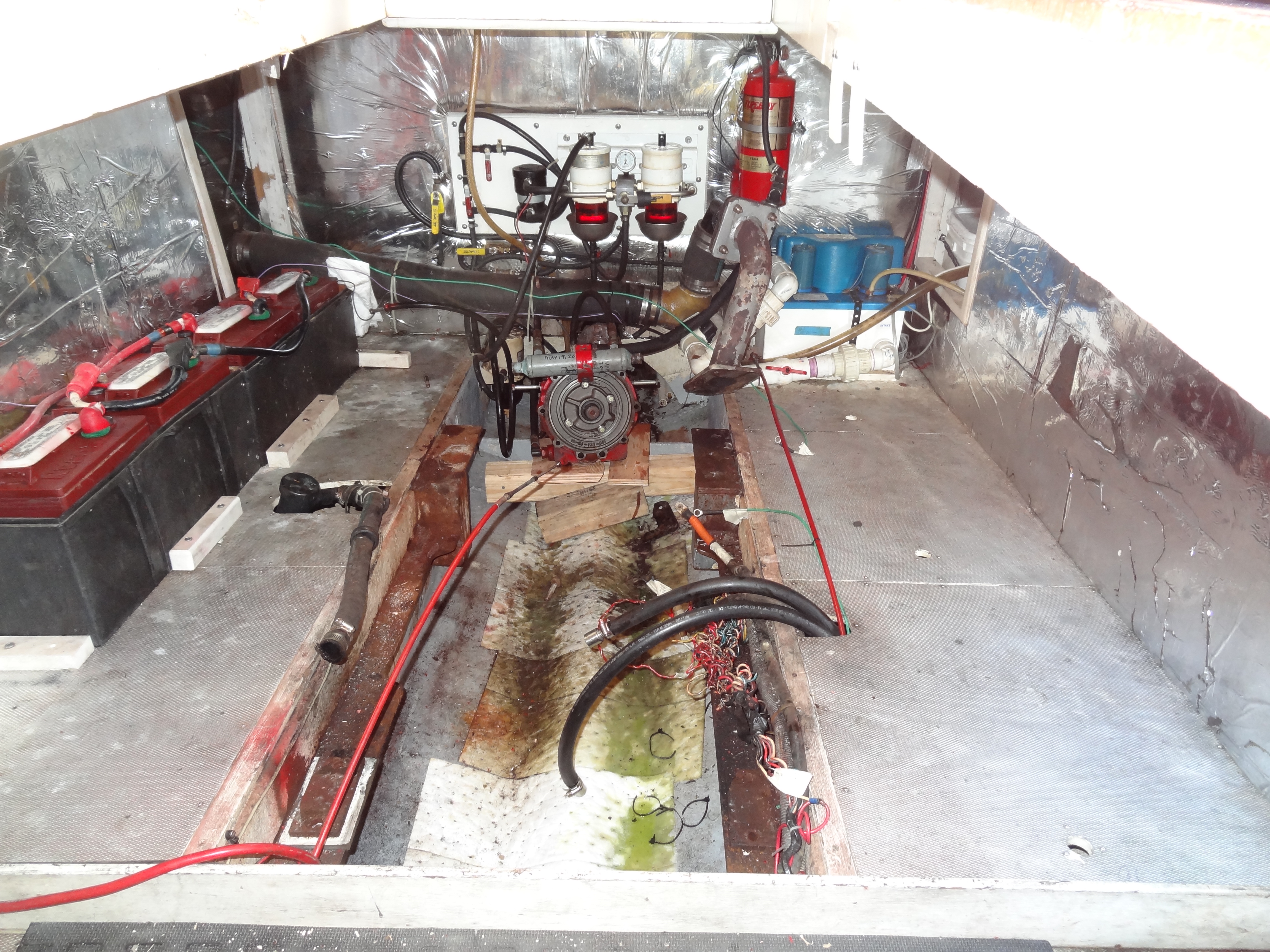
Nearly empty engine room showing part of bulkheads on each side covered in sound baffling material – transmission blocked and left in place

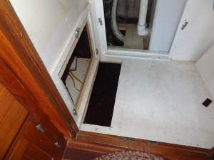
Port side access for second/inboard fuel tank located under settee
Prior to hauling I cut additional access ports through the saloon deck under the settee (port) and sink (starboard) for access to the new inboard tanks where the fuel fill and air vent hoses would attach to the tanks. The area under each cutout was painted with Aluthane aluminum filled urethane metallic coating from Epoxyproducts.com so the tank fabricator would know where to locate the fuel fill and air vent fittings.
Bulkheads removed and tanks cut up and removed from engine room
Port side engine room with bulkhead removed showing port tank in place looking aft
Engine room port side with fuel tank removed
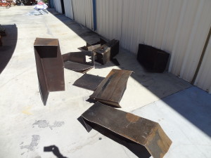
Fuel tank pieces removed from boat
Port fuel tank pieces, another view
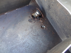
The tank parts had been cleaned by the time I arrived and took these photos. The man doing the deconstruction said that there was “hard gunk” at the bottom of the tanks, extending back about 1/2 way across the inward-sloping bottom of the tank. I was surprised as we’ve had the boat in some rough water (not intentionally) on our cruises and assumed that any “gunk” had been swirled into solution and filtered out via the Racor 500 filters, but apparently this stuff had been there for a long time!
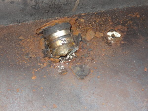
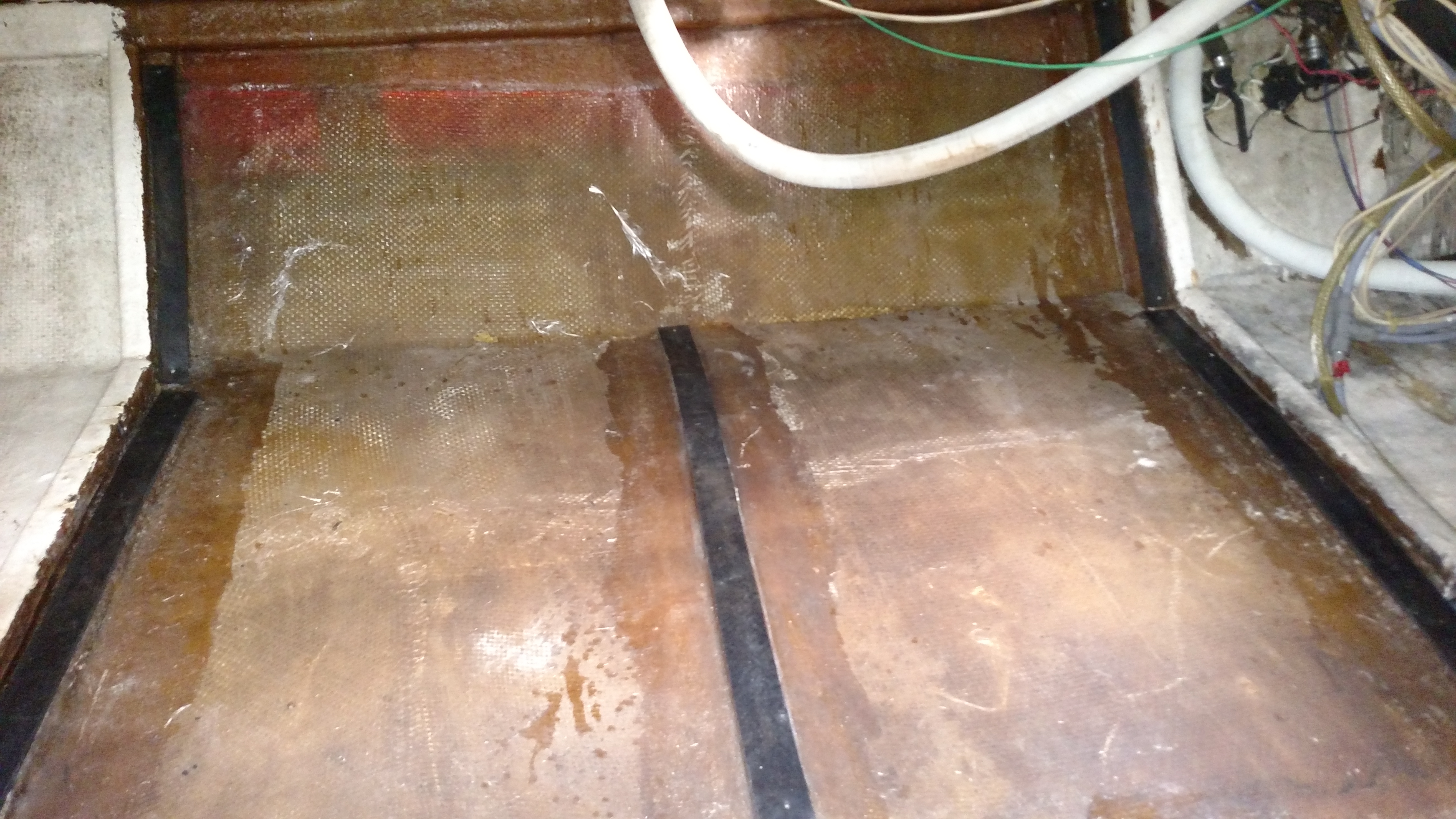
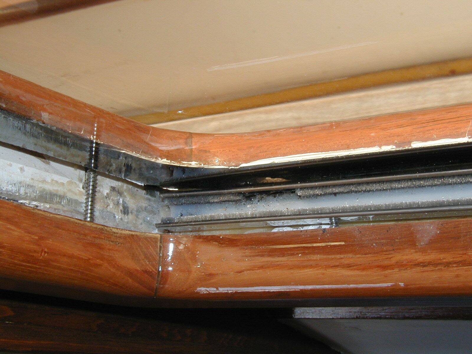
Top of port fuel tank showing fiberglass delaminated from steel tank – the void between the tank and the fiberglass contained water!

Exterior of port tank top around fill and vent fittings showing fiberglass top layer with rusted steel beneath
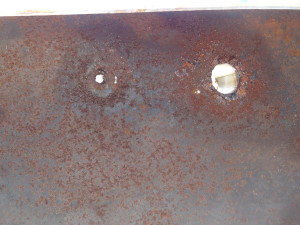
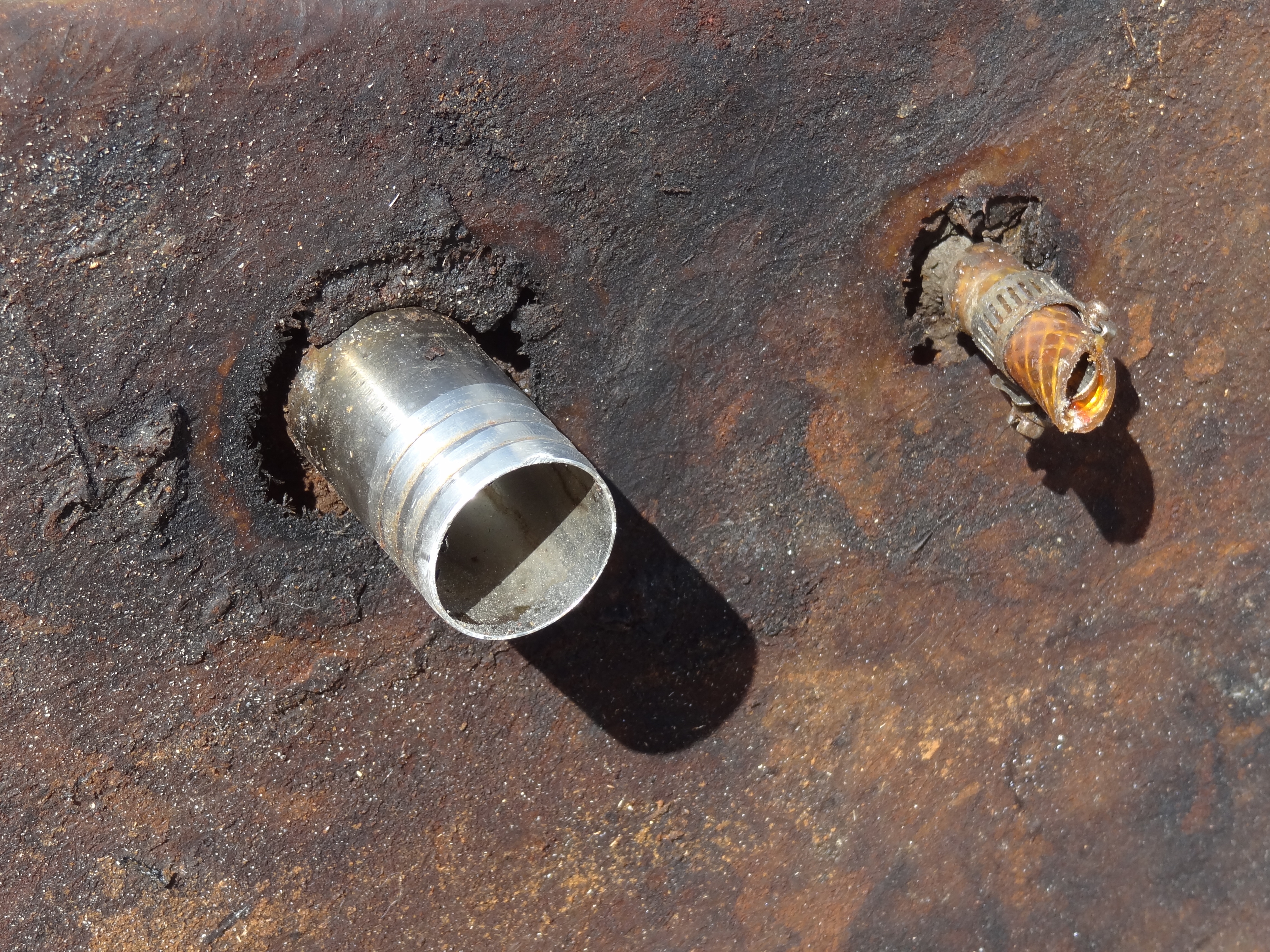
Top side of port fuel tank viewed from inside of tank- showing holes around fill and vent fittings
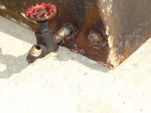
Port tank fuel feed at bottom inside corner at aft end of tank – old gate valve in place – no evidence of rust around the fittings

Engine room starboard side looking forward ready to remove bulkhead to fuel tank
Starboard tank cut out and removed
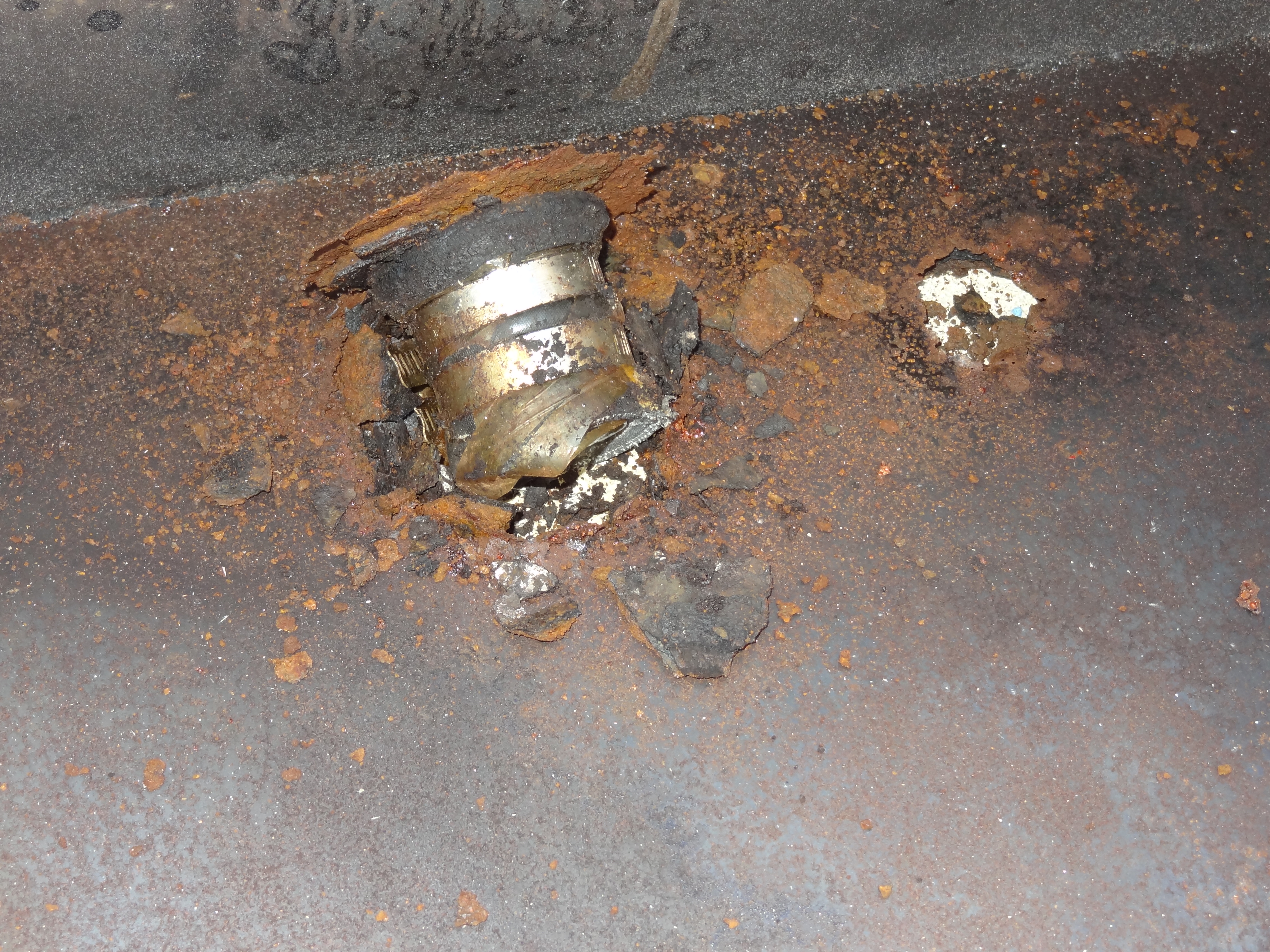
Starboard tank interior around fill and vent fittings – vent tube pulled out of top of tank during removal; fill tube fitting punched through when piece was laid on concrete pad
Starboard tank closeup of fill and vent fittings from inside tank showing rusted steel
Starboard engine room tank location aft end
Starboard engine room tank location forward end
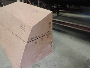
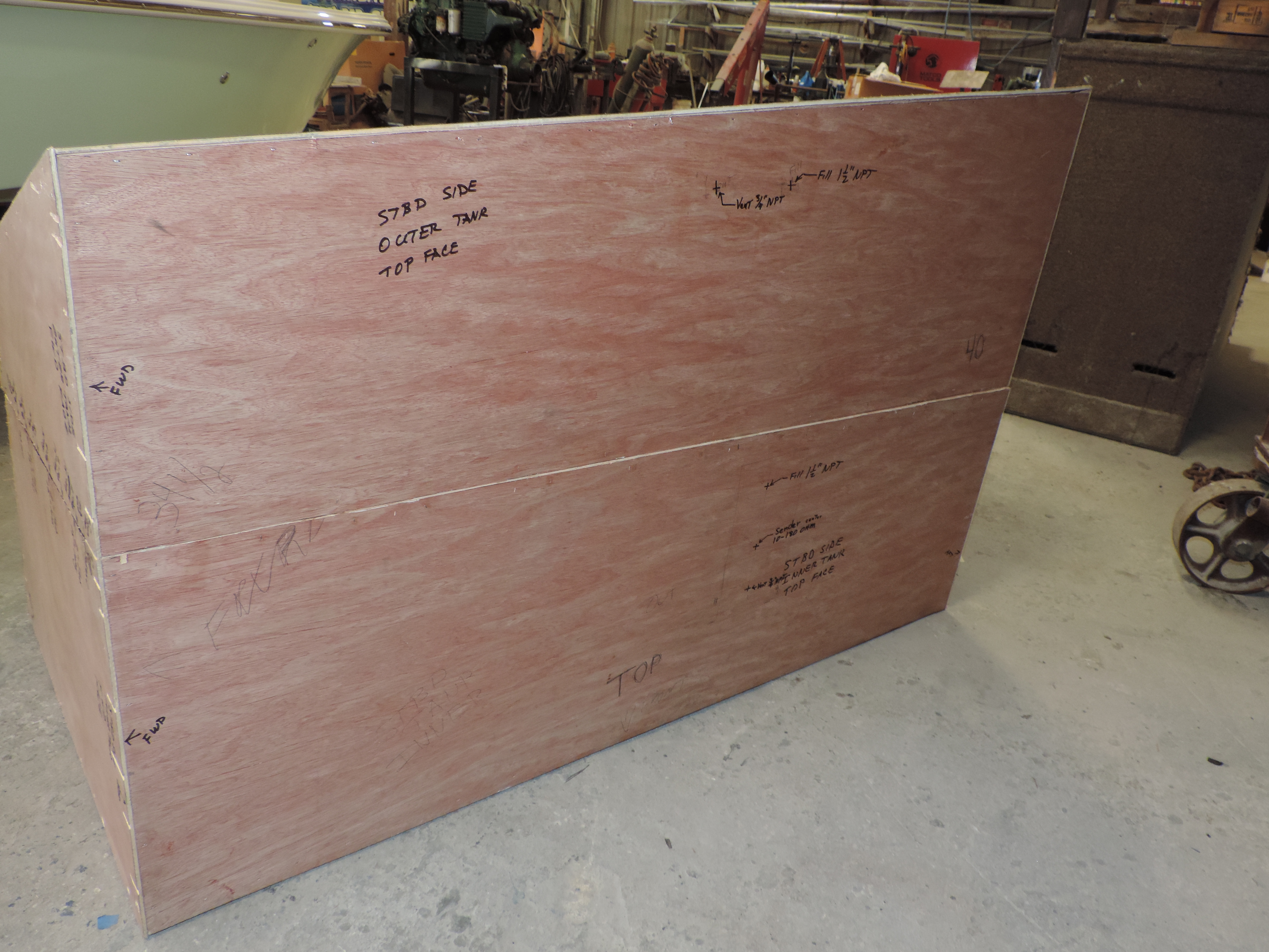
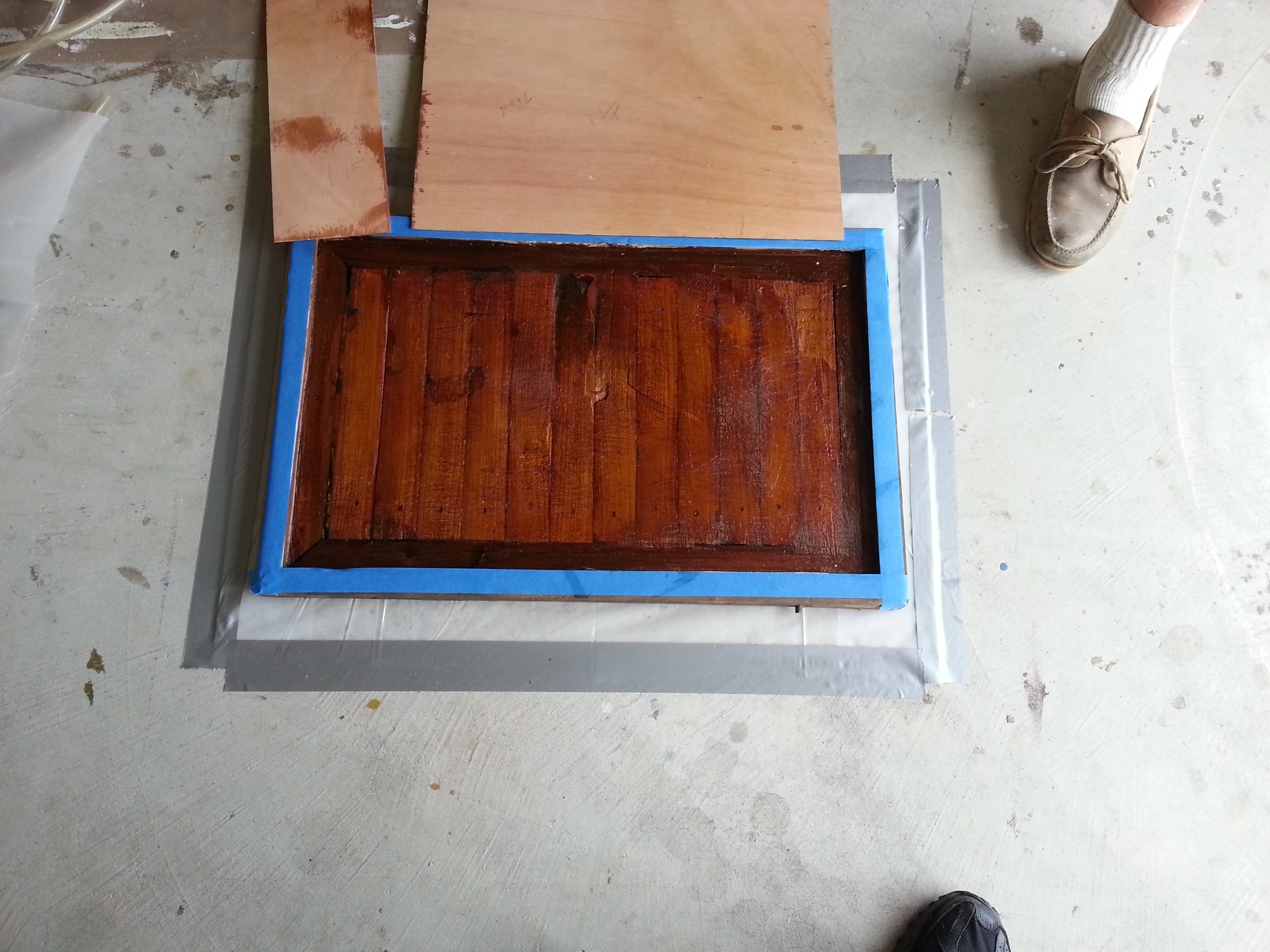
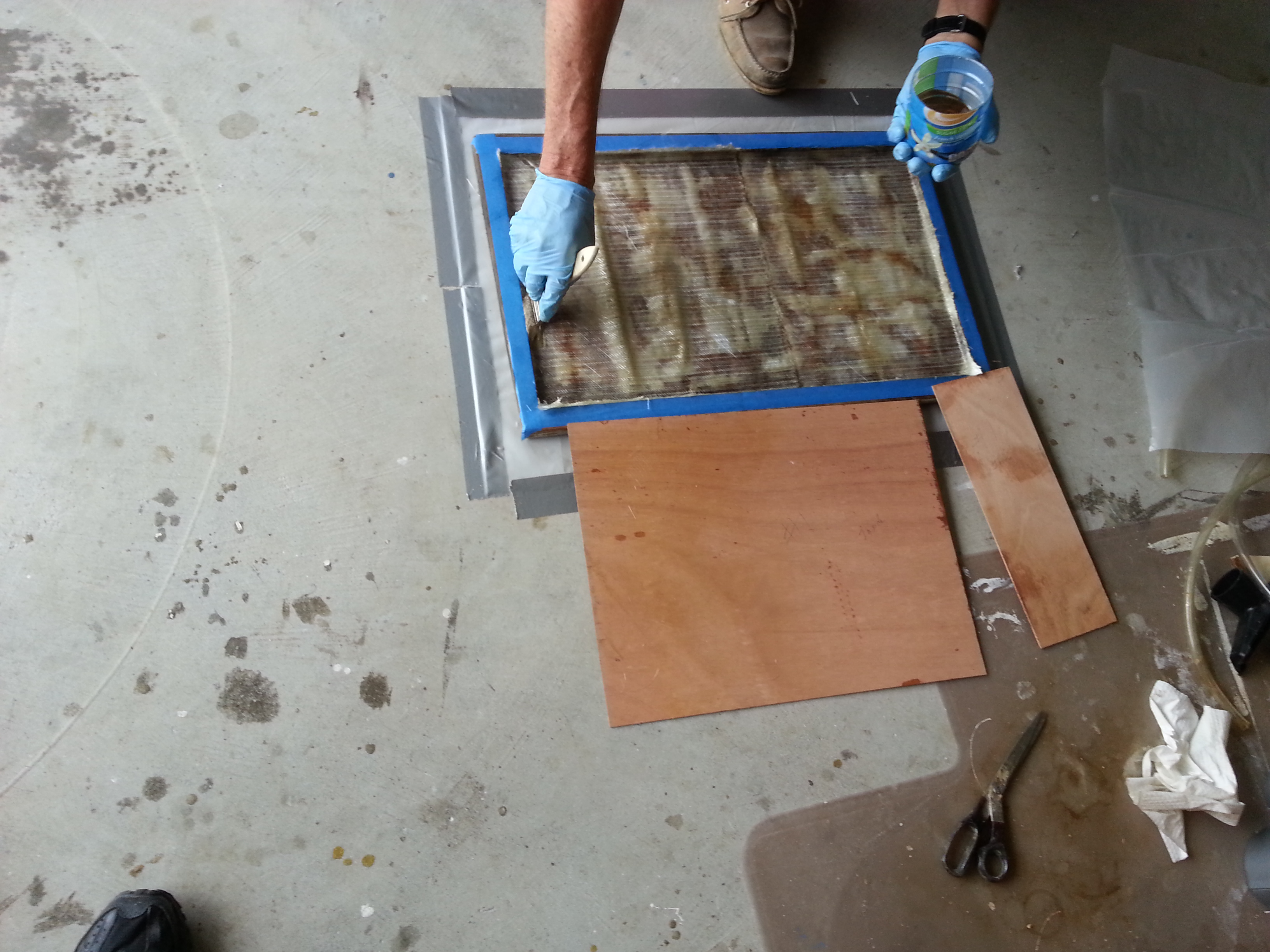
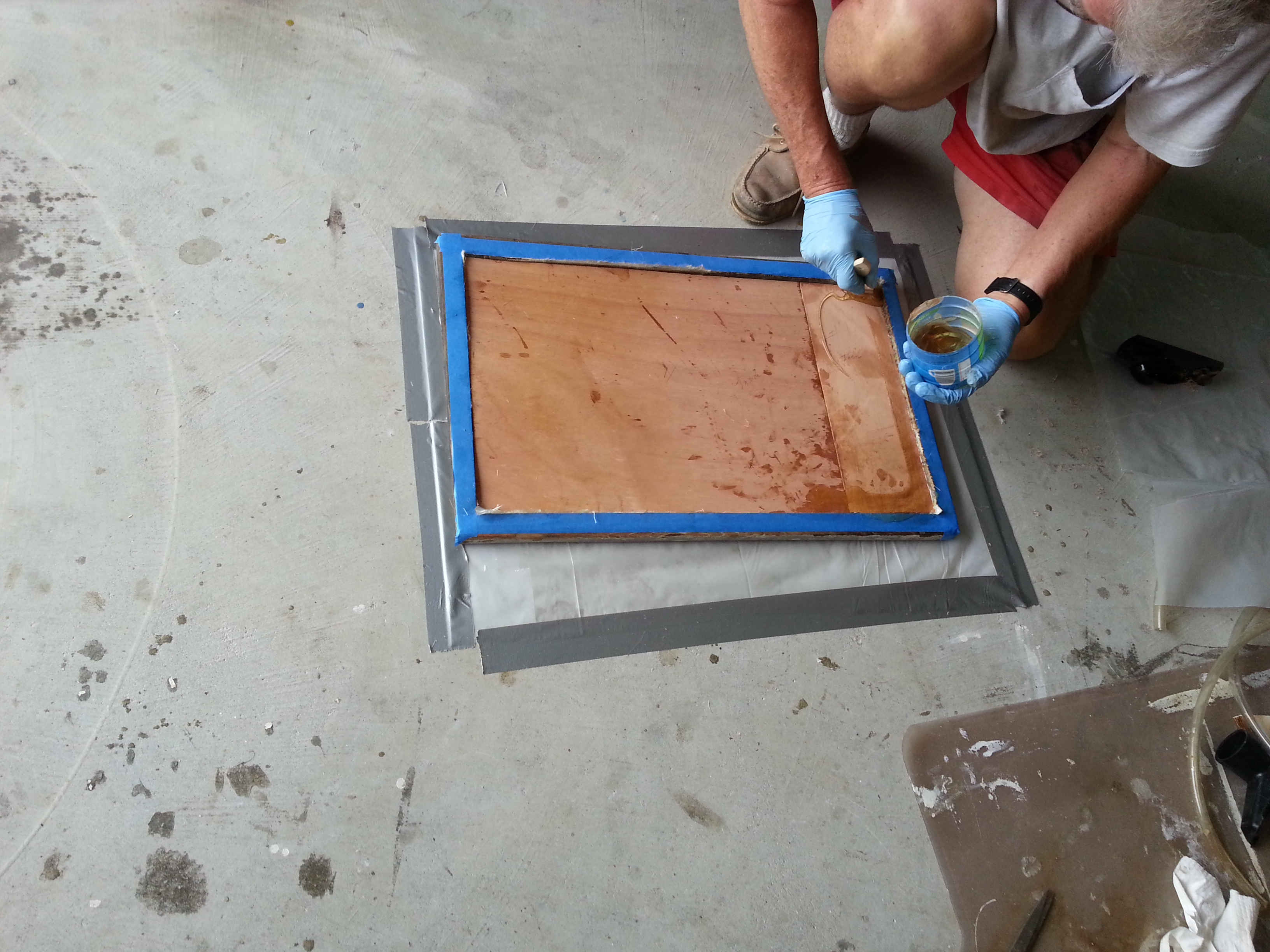
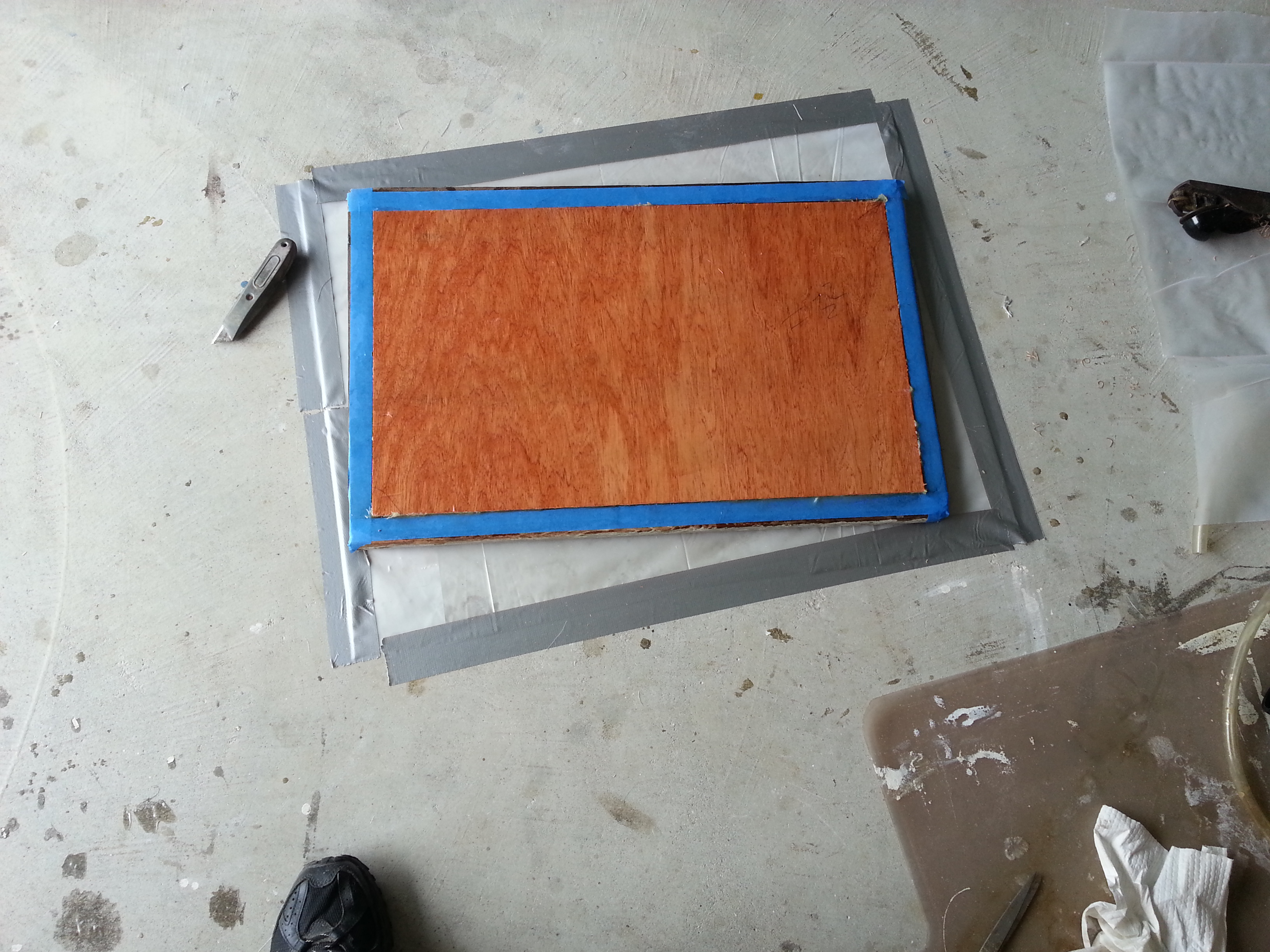
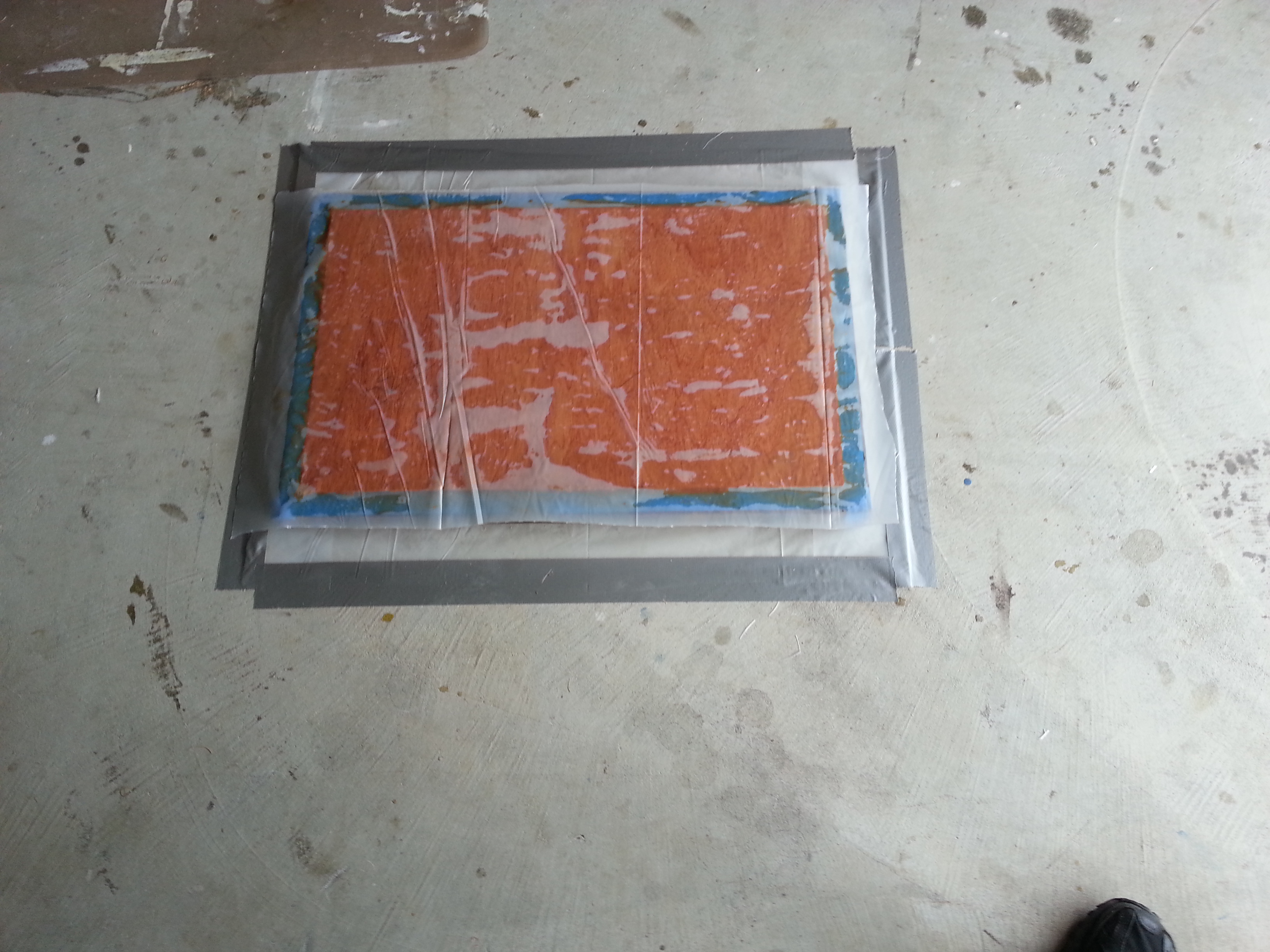
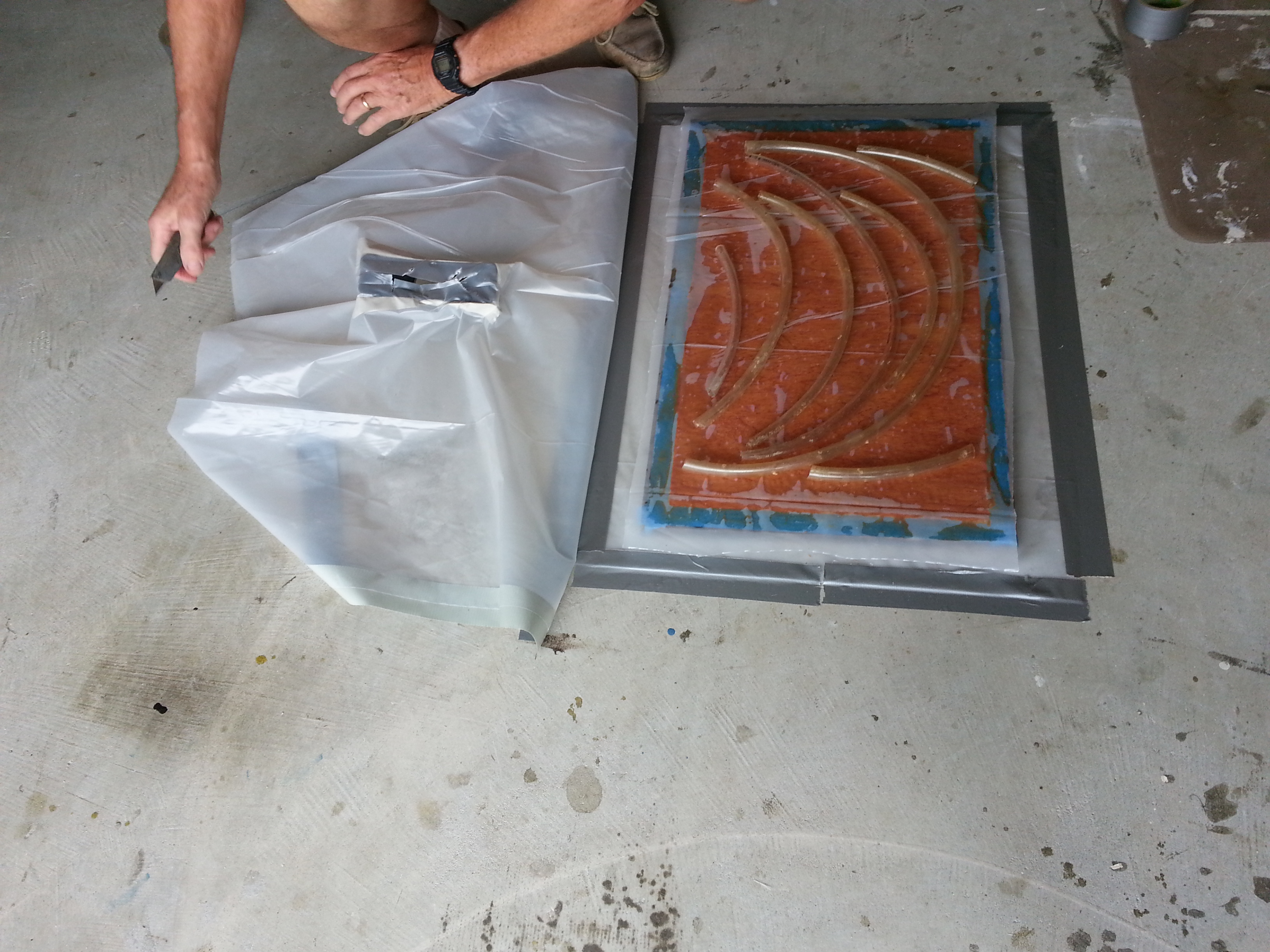
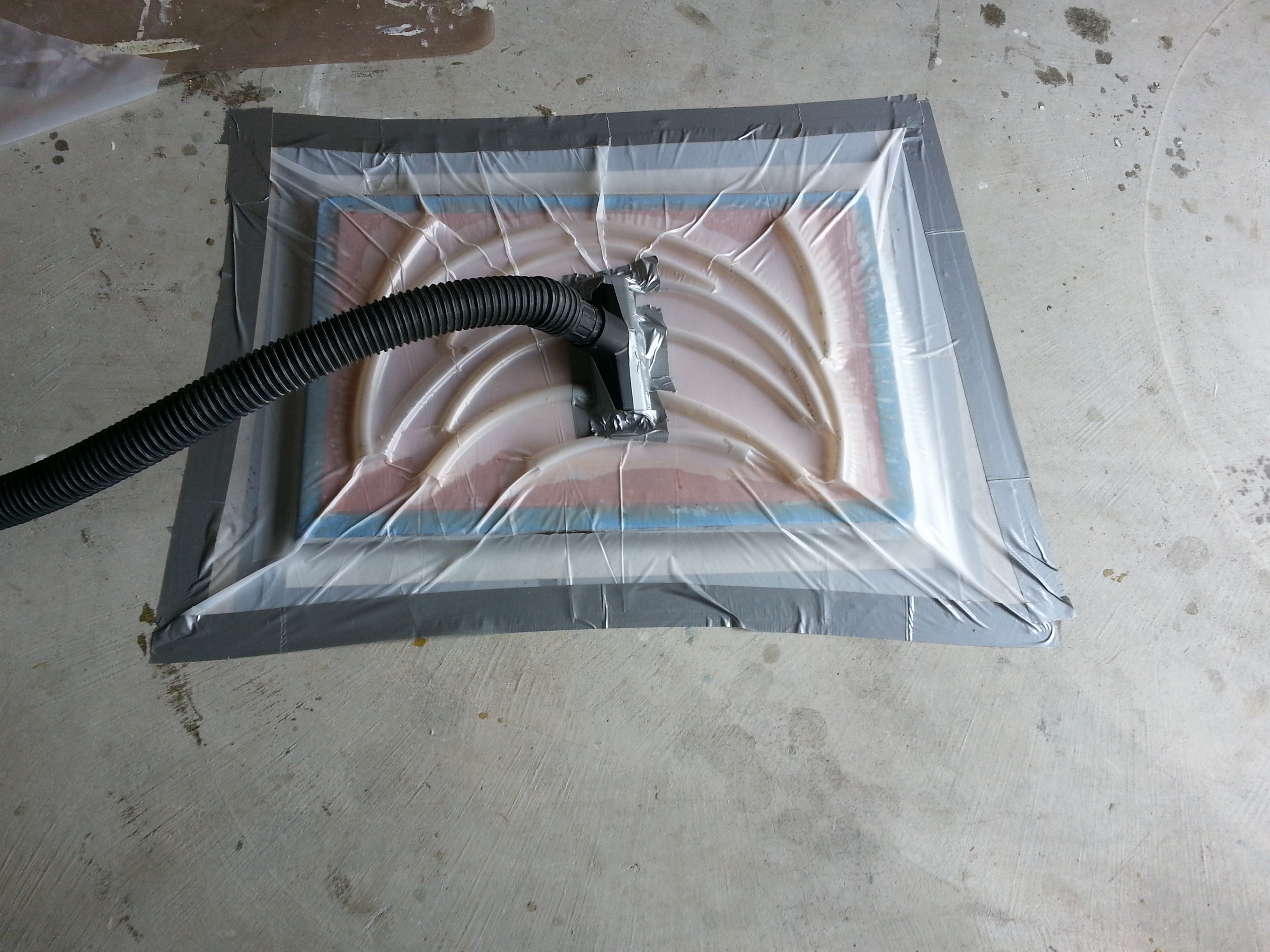
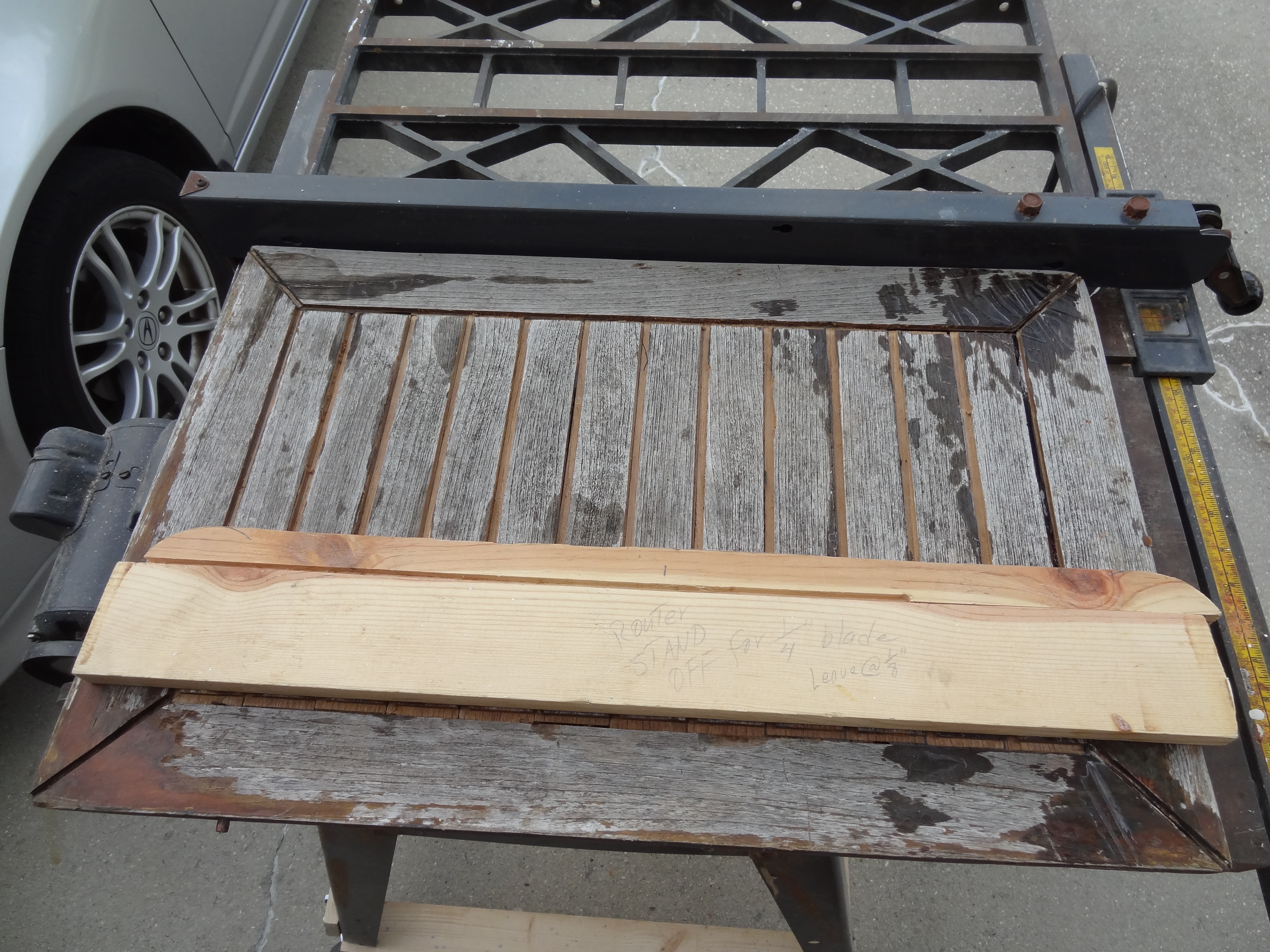
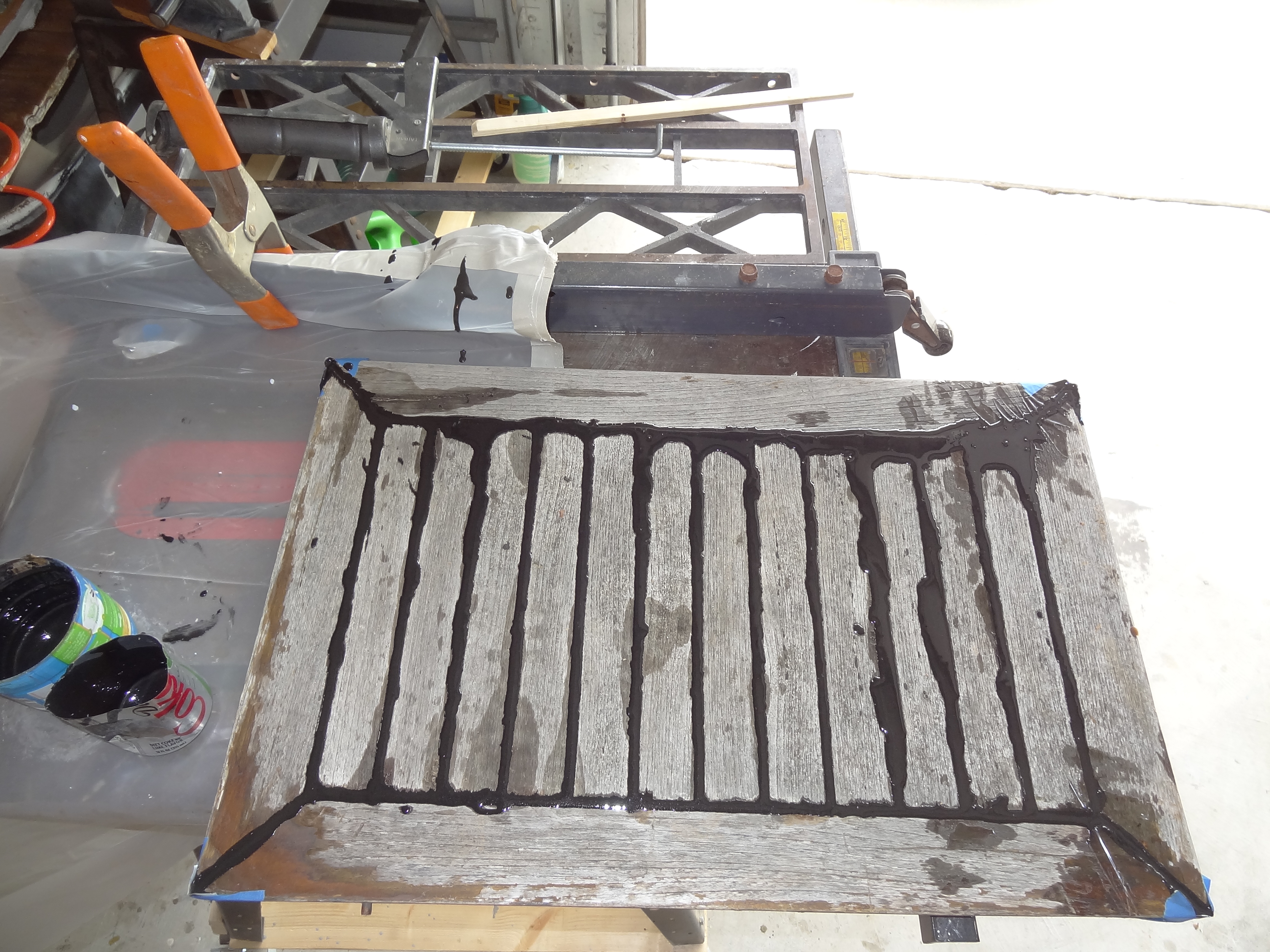
After doing my best to draw out the lines of the new fuel tanks based on the old tanks being split lengthwise, it became apparent that it would be difficult, if not impossible, for the fabricator to duplicate the tanks without a better idea of what would be needed. Consequently, after discussions with the boat yard and the fabricator, it was decided to build full-scale mockups of the new tanks. It was a good decision, as it turns out. The mockups built by the yard still needed to be tweaked a bit after fitting them in Sanderling, and after doing that we now have mockups that we know will fit properly in the space occupied by the old tanks. The yard essentially built a mockup of the old tanks (the port and starboard tanks were slightly different from each other) and then cut out a 3/4″ slice 19″ from the inboard side of the tank to create two smaller tanks that will fit through the saloon door and the opening to the engine room and can then be maneuvered underneath the deck to their resting place. The 3/4″ spacing is to permit a length of 1/2″ starboard to be placed between the tanks on each end to permit a gap between the two tanks (with an extra 1/4″ left over for a little “play” if necessary. The tanks will then be joined together with two sets of “ears” or “tangs” on the ends of each tank (near the top and bottom) that will receive a nut and bolt that when tightened will pull the two tanks together. The location of all the fittings will be marked on the mockup so the fabricator will know exactly where to place them.
For the fittings we’ll be welding NPT fittings of three different sizes into the 1/4″ aluminum tanks to receive corresponding male fittings. Fuel fill fittings will be 1 1/2″ NPT, air vents will be 3/4″ NPT, and pickups and returns will be 1/2″ NPT. The fuel level sender will be located on the top of the larger inboard tanks (rather than on an inspection port on the side of the tank as was the case with the original tanks). All of the fittings will be located beneath access hatches in the deck above, located under the saloon sofa, the side decks and the galley sink. There will be no sight tubes as they really are not necessary for determining the amount of fuel remaining in a tank – the hourly fuel burn rate is just as accurate without the potential danger associated with sight tubes, plus the electric fuel level senders will provide a good approximation of the amount of fuel in the tanks.
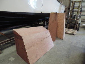
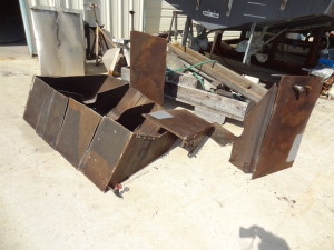
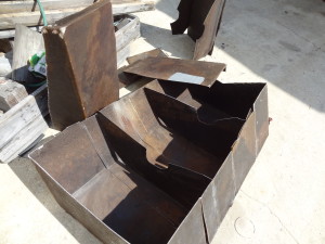
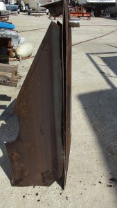
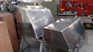
Foreground: starboard tanks laying stacked together. Background: port tanks standing on aft ends.
Forward end of starboard tanks.

Starboard tanks top side.
FANTASTIC NEWS! TODAY (MARCH 26TH) I RECEIVED A CALL FROM DAVE AT SUNSHINE WELDING TO LET ME KNOW THAT THEY WERE GOING TO START WORK ON THE TANKS!!! Dave, Mark Smith (boatyard owner), and the welder are going to look over the mockups and the engine room this morning to get a better idea of what needs to be done, will take the mockups to Sunshine Welding’s shop (about 100 yards from the yard) and the welder will get to work. Dave estimates the work will take about one day per tank – hopefully the tanks will be finished by the end of next week.
April 1st – no joke! Received a call this morning from Dave at Sunshine Welding to say that the fuel sender which I hoped would be able to fit into the tank (the type with the swinging arm) would not fit in the tank because of the baffles that are required to keep the tank steady and that they did not have the sliding type with the specified ohm range of 10-180 ohms. He had done some research and sent me a link a web site that might have the sender with the required ohm range. The clearance at the location in the tank is 26 inches.
After a little online research, it became apparent that the swinging-arm type sender with the required ohm range is more readily available, but that there is one company that makes the sliding type right here in Florida. The senders come in a large variety of lengths from 4″ to 60″ and can be made to accommodate any ohm range. A quick call resulted in an order for two 25.5″ senders with a range of 10-180 ohms. Cost was reasonable (less than I anticipated) and they might be shipped as early as Friday (April 3rd).
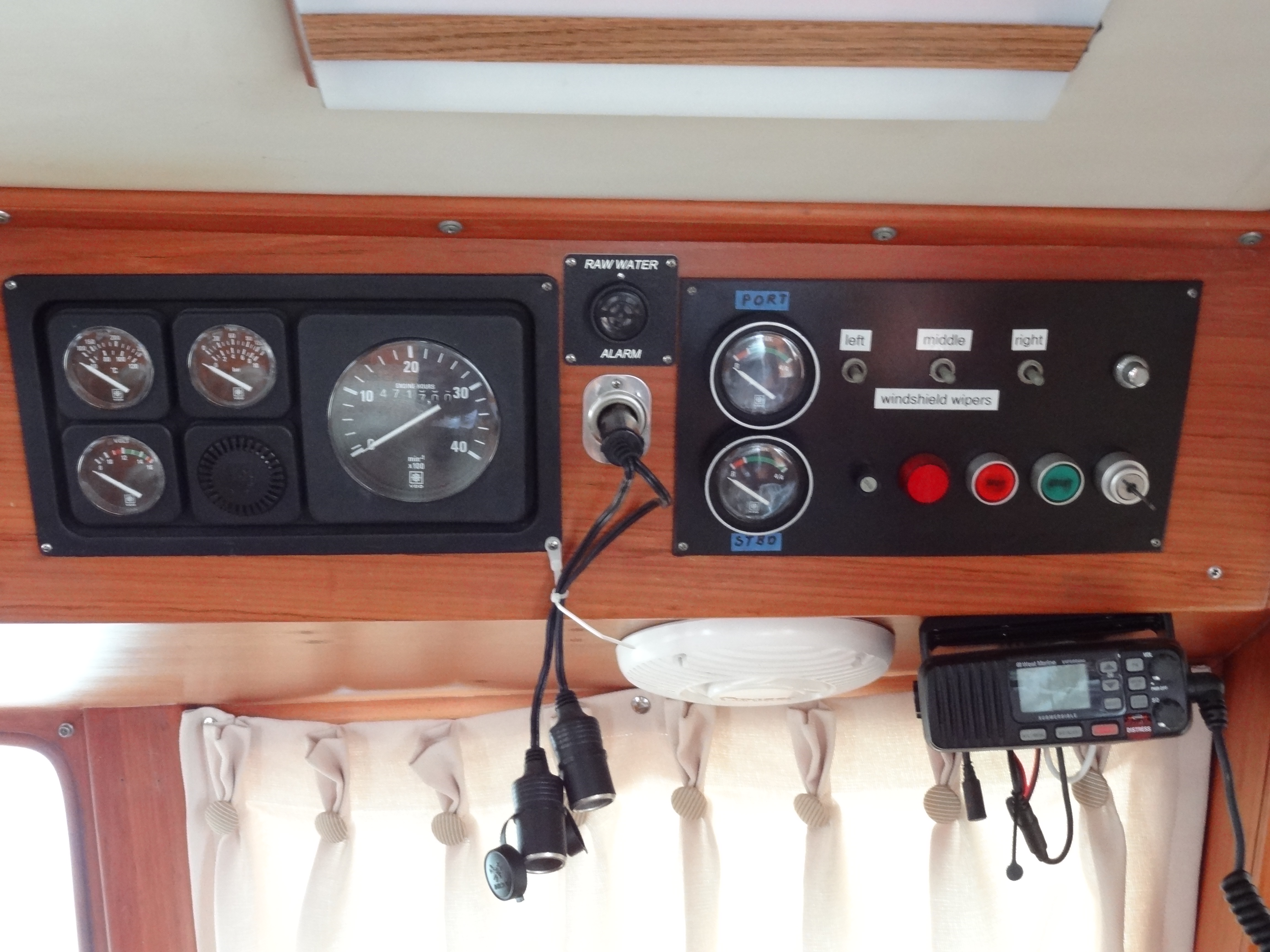
This is the style of gauge that fits our new tanks:

Apparently, most modern senders and gauges use a 0-90 ohm range, but the sender must be matched to the gauge (and vice versa). In our case, since we already have VDO instruments including the fuel gauge circa 1987, only a gauge with 10-180 ohm range will work.
Here’s a link to the WEMAUSA web site showing the sender: http://wemausa.3dcartstores.com/SSSSSL-Diesel-Fuel-or-Water-Level-Sensor-4–60-in_p_9.html
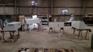
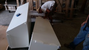
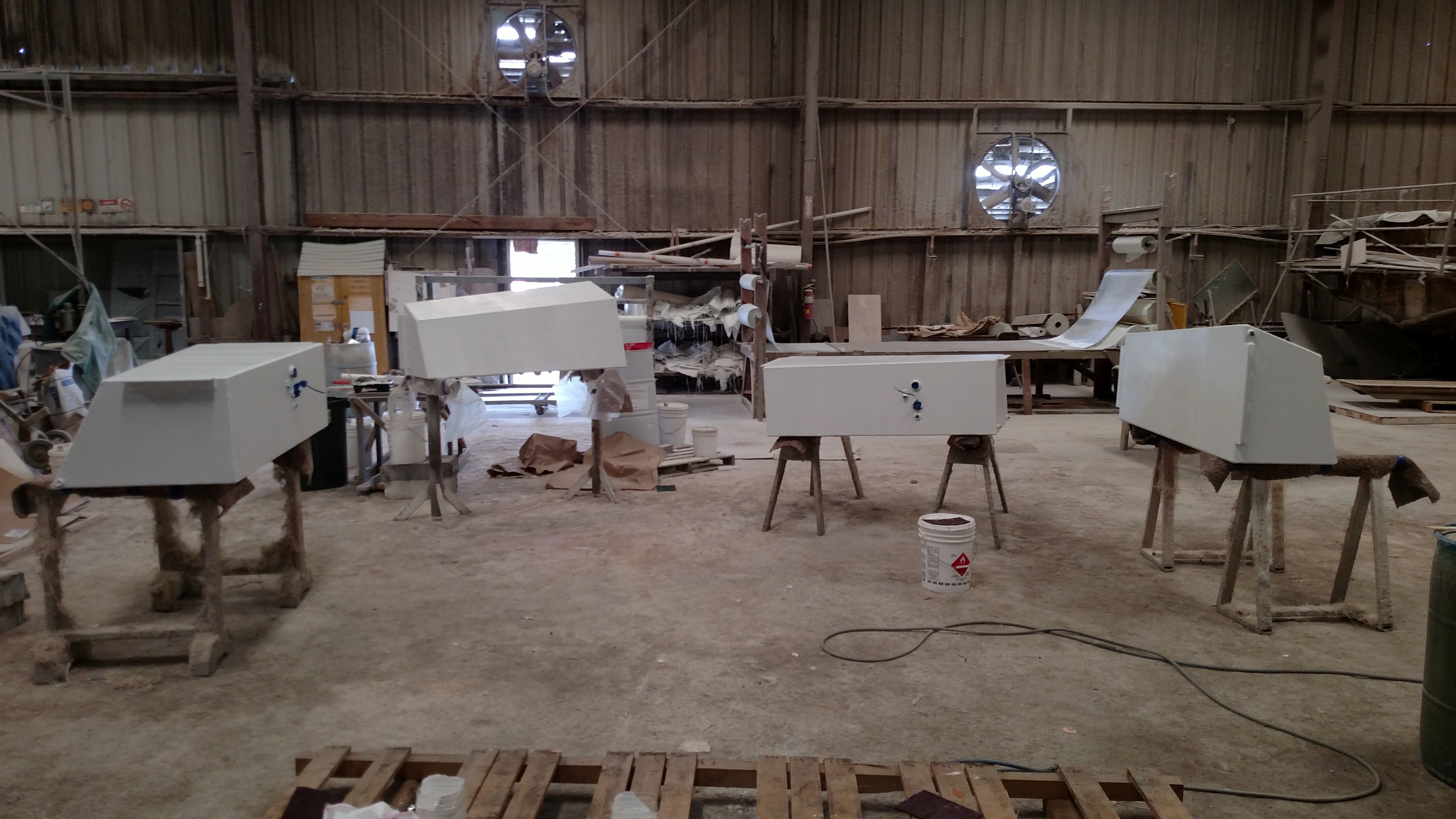
April 6, 2015. Fuel tanks tack welded in shop almost finished.
Here is a pic of the tanks in the shop. After welding the seams the fuel senders will be installed and the tanks pressure tested. Should be delivered to the boat yard tomorrow (April 7th) where they’ll be painted with two-part epoxy paint, then installed in Sanderling! Yeah – we’re almost ready to launch.
Installing the new tanks and replacing the bulkheads and engine
Update April 9, 2015
The tanks were finished on April 8th and delivered to the boat yard on the morning of the 9th. Interestingly, when I paid the final bill at Sunshine Welding I was given Coast Guard certification stickers to put on all four tanks indicating that they had been pressure tested to 4 PSI and that each pair of tanks (one pair each side) were 143 gallons and 130 gallons for a total of 273 gallons per side (this is based on a calculation by the fabricator) for a total of 546 gallons. All these years we’d been assuming that the original tanks held a total of 200 gallons each, based on the boat builder’s brochure and what we were told by the previous owner (but there was no CG certification attached to the original tanks). Each pair of new tanks were designed to be approximately the same size overall as the original tanks, minus a 3/4″ slice removed from the center when the two separate tanks were created. Now it seems that we’ve had around 550 gallons total in the tanks all along. That would explain the larger than calculated amount of fuel remaining in the tanks when they were emptied prior to removal from the boat. I had calculated that there was less than 75 gallons remaining between the two tanks; in fact, there was around 150 gallons remaining in the two tanks.
April 17th, 2015 – Tanks in Delta Boats shop with four coats of epoxy paint.

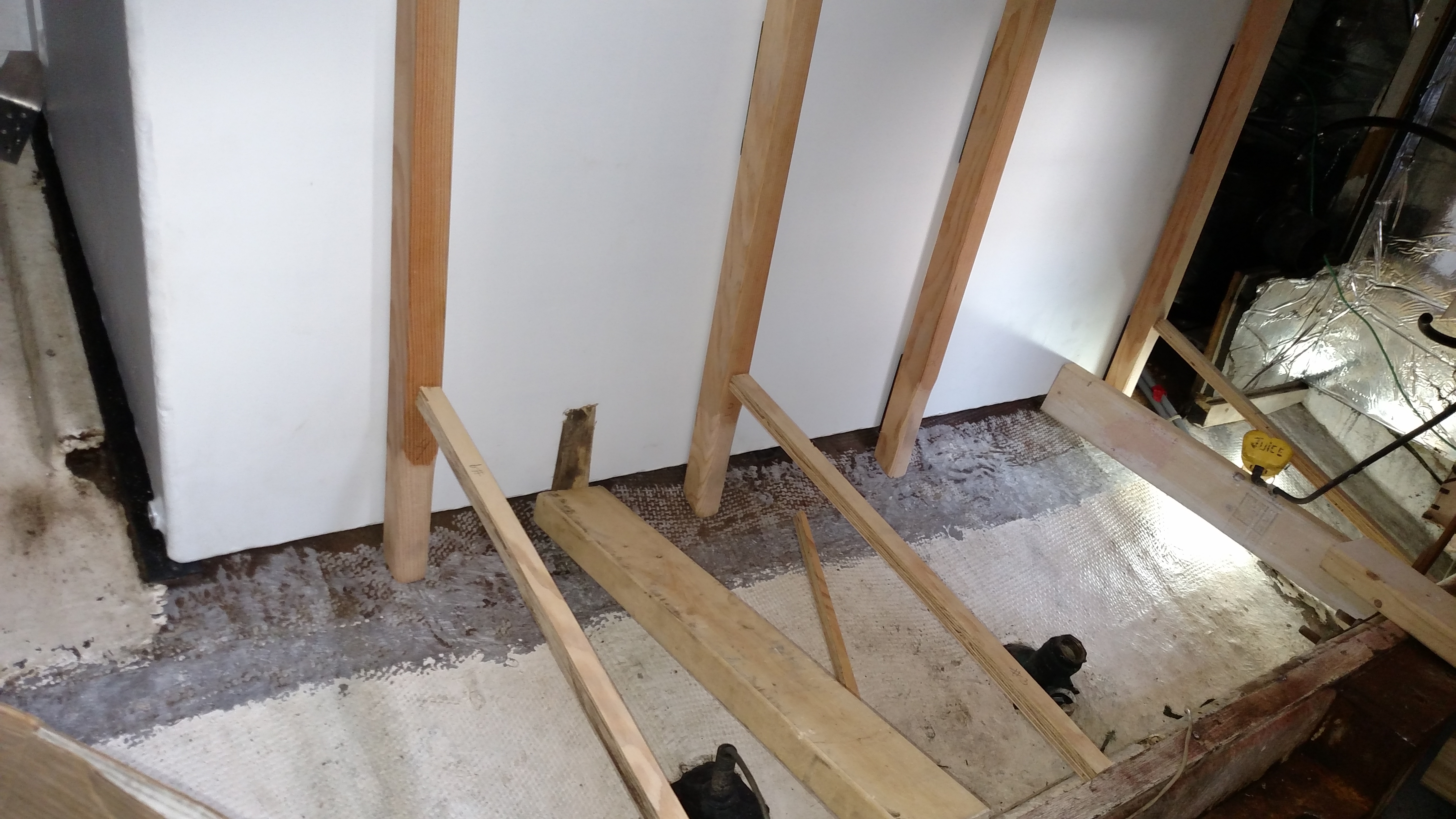
April 24, 2015. Starboard side of engine room with 1/4″ rubber strips covering the raised planks where the tanks will sit.
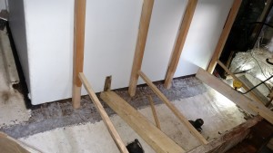
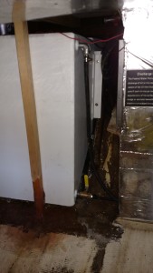
April 29, 2015. Starboard fuel tanks in place with upright frames glassed to hull
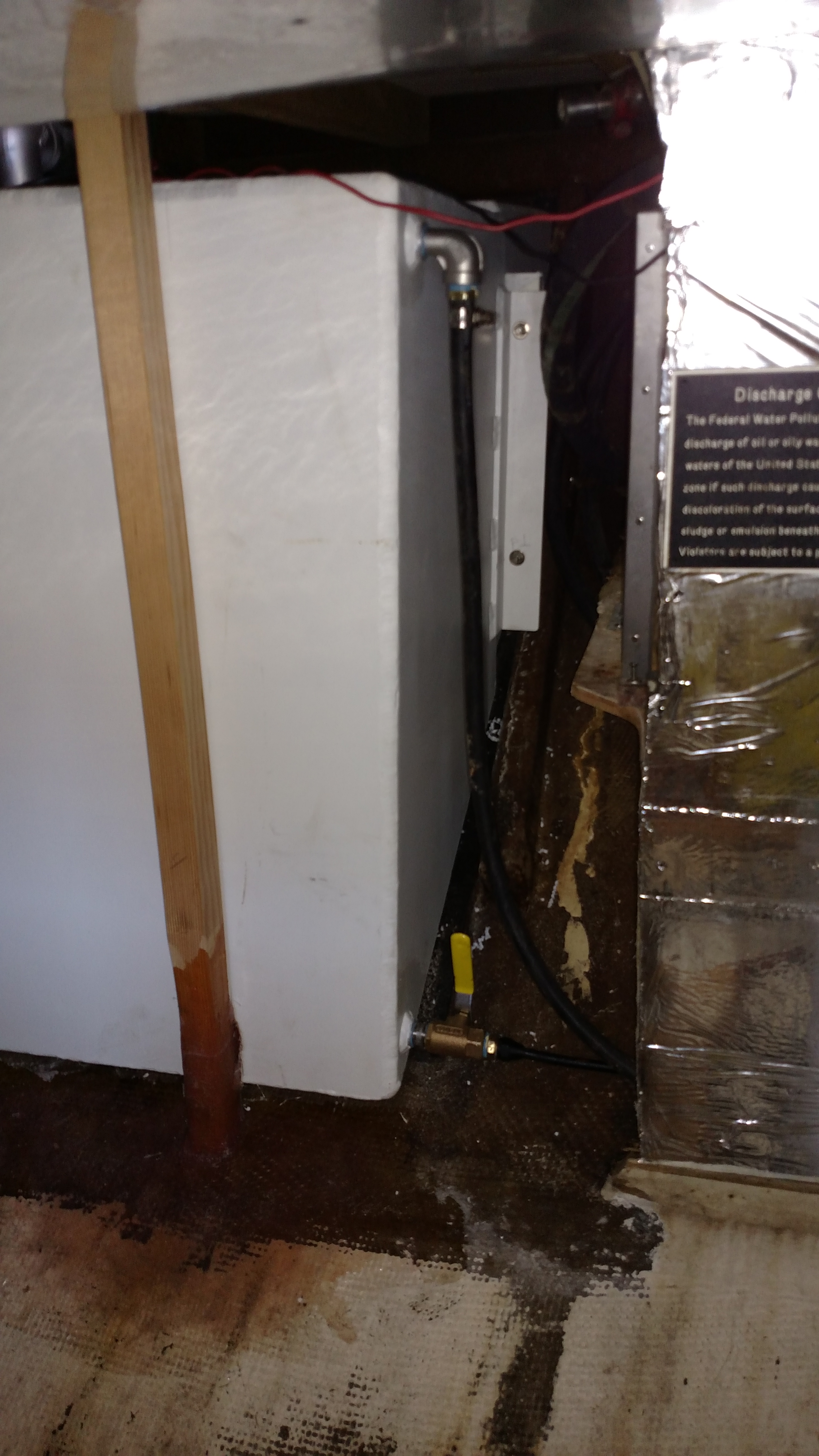
May 4, 2015. Port tanks before installation with “Juice” fastening spacers and drilling alignment holes for bolts
May 5, 2015. Port tank forward end showing genset pickup (bottom) and return (top) in place

May 5, 2015. Holes cut in stbd deck for fuel fills; sealed with thickened vinylester resin
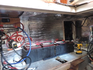
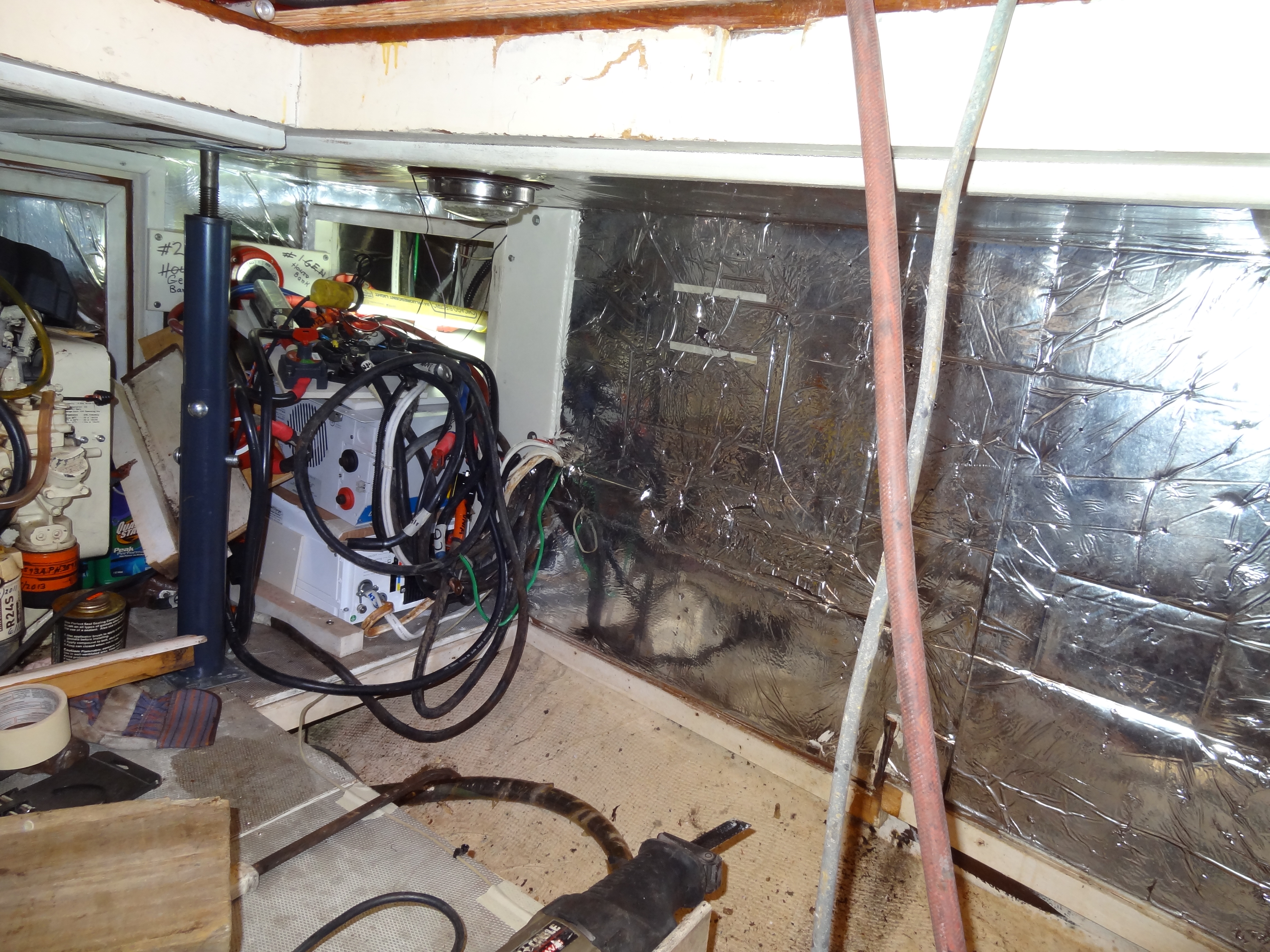
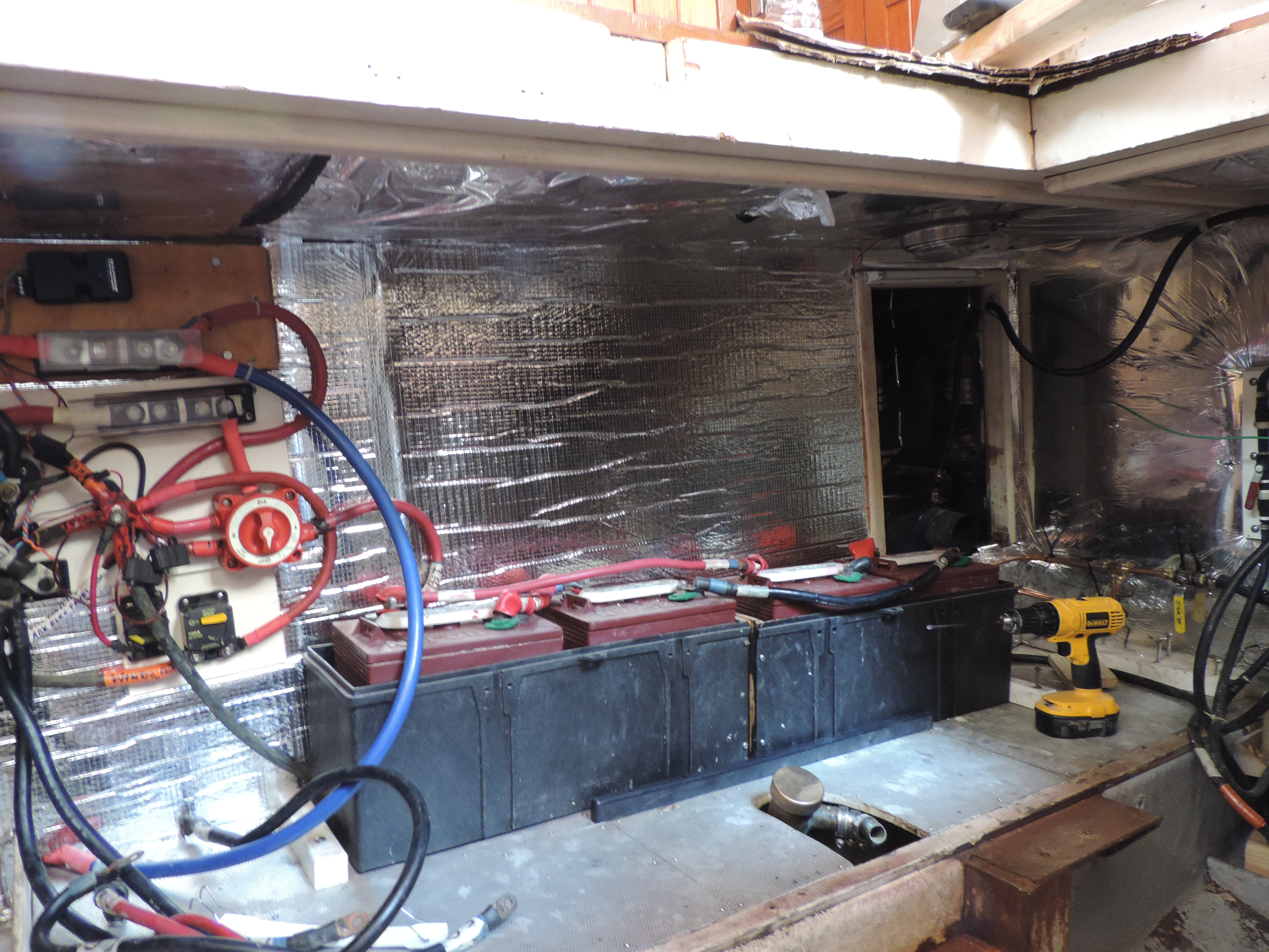
May 22, 2015. Port side engine room with bulkhead, sound deadening and electrical wiring back in place.
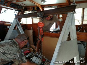
May 26, 2015. Lowering the engine into the engine room. Almost there!!!
May 27, 2015. Juice reconnected the myriad electrical lines to the engine, replaced some worn fuel hoses that were discovered after the engine was in place, and tested the fuel lines he had installed earlier. A slight leak at one of the copper line fittings required a 1/8 turn tightening, and that was it! He turned the on/off switches to the battery banks to the “on” position and I checked the voltage of the banks using the Magnum ME-ARC50 remote control – 12.4 volts; not bad for sitting in a storage area for three and a half months. Juice also refastened the exhaust riser and replaced the worn exhaust hose to the muffler.
May 28, 2015. Juice replaced the main negative cable leading to the starter and the temperature sensor on the exhaust hose leading to the muffler. I connected a three-prong to 30amp adapter to a long extension cord and started the Magnum inverter/charger, checked all the remote settings, then put the inverter/charger in charging mode for about five hours. The initial charge was at 80 amps, but it quickly started dropping and ended at about 12 amps. At that point Juice used the Walbro inline fuel pump to ensure that fuel was flowing through the line to the engine, connected a water hose to the engine raw water intake and I pushed the starter button – – – and the engine started on the second try! Great news! I ran it long enough to see that the Balmar alternator was working properly and that the new fuel gauges were working, then shut her down for the weekend.
There is still a thru-hull and valve to replace under the forward sink and a vent line to complete from the propane locker to the exterior of the hull (thru hull vent is in place but hose hasn’t been run), but that will all be accomplished on Monday morning before we are launched at 0900. We should be underway for our marina by 1030 at the latest! That will be an even better day!
June 1, 2015 Back in the water – YEAH!
After almost four months (since February 9th) we’re back in the water. Will post a few launching photos later. After ensuring that the only “leak” came from the very dry stuffing box when Sanderling was set in the water, we started the engine only to see that the oil pressure spiked. We felt fairly confident that this was due to the electrical connection at the oil pressure sender being placed on the wrong lead, so Mark got Juice while we tied to a floating dock at Cape Marina. Within minutes Juice had fixed the problem and we were on our way. When we called the lock for an opening we were told that they would be closed for underwater repair work until 1700! Nothing on their web site to indicate any closure, but we didn’t have any options at this point. We tied up to the east wall leading into the lock and waited and cleaned and checked “things” and waited some more. Finally, about 1630 a commercial tug called the lock for a passage indicating that “their” divers were now out of the water, and by 1645 we were in the lock and on our way. Arrived at our marina about 1910, put Sanderling to bed, and left to find dinner and retrieve a car which had been left at the boat yard.

Ready for lift-off!
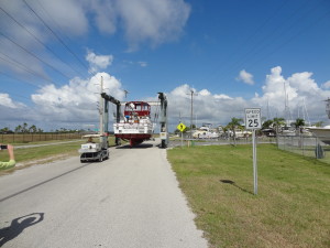
On the road again!
Ready for splash-down!
June 1, 2015. We’re back in the water again – yeah! Now for a little more work at our marina and we’ll be on our way north.


")


