Project: Repair broken handrail gate latch

Repairing Broken Handrail Gate Latch

Sanderling is a Defever 41 built in 1987 with lots of teak – window frames, hand rails (with three gates), cap rail, topside trim and seats, and deck. We’re willing to put in the extra work that is required to enjoy the warm appearance of the teak. Our former trawler had the same type of bright-work and we knew how to deal with it. One thing we hadn’t dealt with before was a broken gate latch.

Sanderling’s three gate latches consist of two similar stainless steel parts: one with a sliding pin fixed to the gate, and the other, with an L-shaped piece with a hole which the sliding pin engages, attached to the stationary hand rail. The “broken” gate latch prevented the swinging end of the gate on the starboard side from fastening securely. This is our most used gate since we always try to saddle up to a dock on the starboard side due to left-hand engine rotation. I considered it a safety hazard, particularly when underway, since a slight amount of upward force on the gate would cause it to open. When the gate latch “broke” part way through this past summer’s cruise, I didn’t want to take a chance that dismantling the latch might result in loss of the gate completely, so I didn’t attempt repairs until we reached our home marina this fall. We just had to be extremely careful when traversing the side decks near the broken gate.

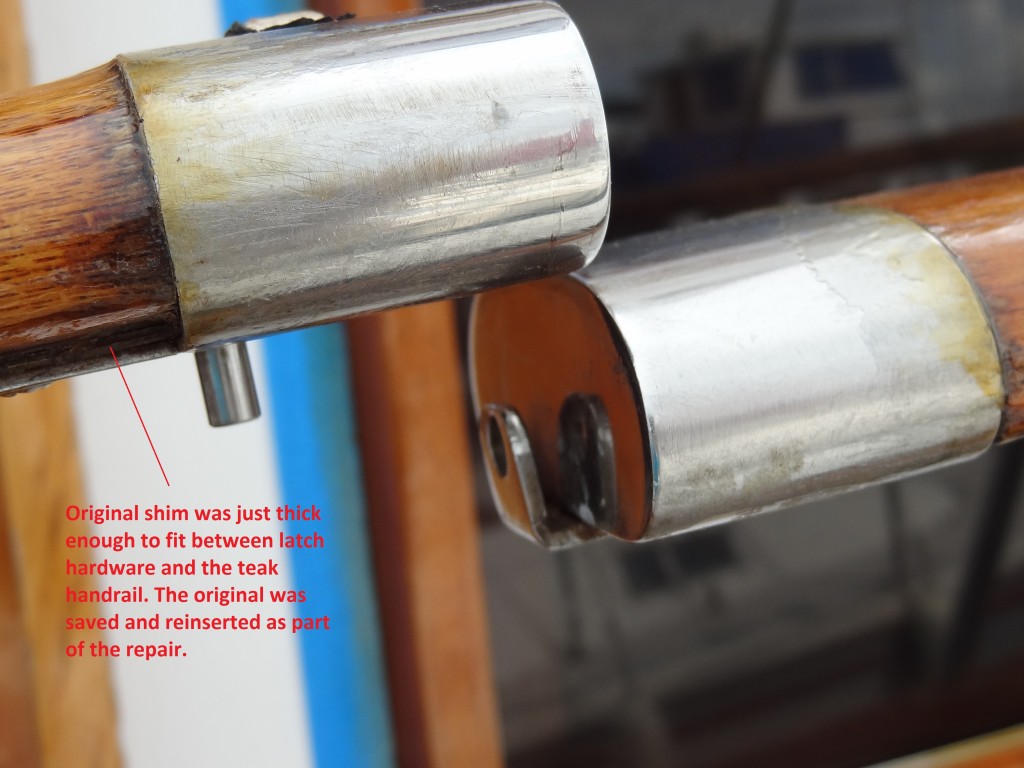
The first photo shows how the gate latch parts (the stationary part on the rail and the part on the gate itself) go together as the gate closes. The photo also shows the location of the shim that is inserted between the tang on the latch and the gate, and the L-shaped piece with the hole that engages the pin and holds the gate securely. This type of latching mechanism seems to be common on trawlers with teak hand rails.

The latch slides over the end of the gate and is fastened with five screws from the bottom. The first concern was whether removal of the hardware would require the use of heat and as a consequence damage the underlying teak. Once I removed the screws and started gently tapping the edge above the teak rail with a small hammer and large flat-blade screw driver, the latch moved slowly with each tap, but was obviously fit quite snugly on the rail. Fortunately, no heat was required even though there may have been some caulk or adhesive used when it was originally put in place. There was also the need to hold the gate as firmly as possible so as not to damage the hinge part of the gate mechanism, and to hang onto the latch so as not to have it fall overboard if it suddenly came loose and jumped out of my hand!

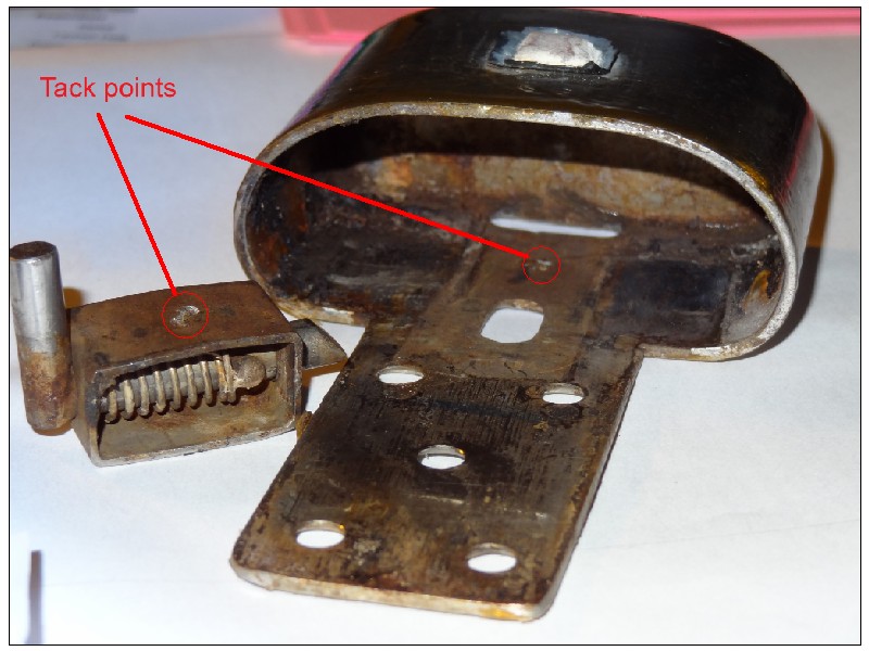
Once it was successfully removed, the problem became apparent. The small 4-sided box that holds the movable pin and spring assembly had come unfastened from the main frame of the latch.

The second photo shows the box with spring and pin (turned upside down from it’s normal position) and the apparent single-weld attachment point with the corresponding attachment point visible inside the stainless latch frame. The beveled end of the pin engages the hole in the corresponding fixed latch, while the upright portion of the pin extends below the latch and is moved back with a finger to disengage the pin from the hole. The spring holds the pin in it’s closed position.

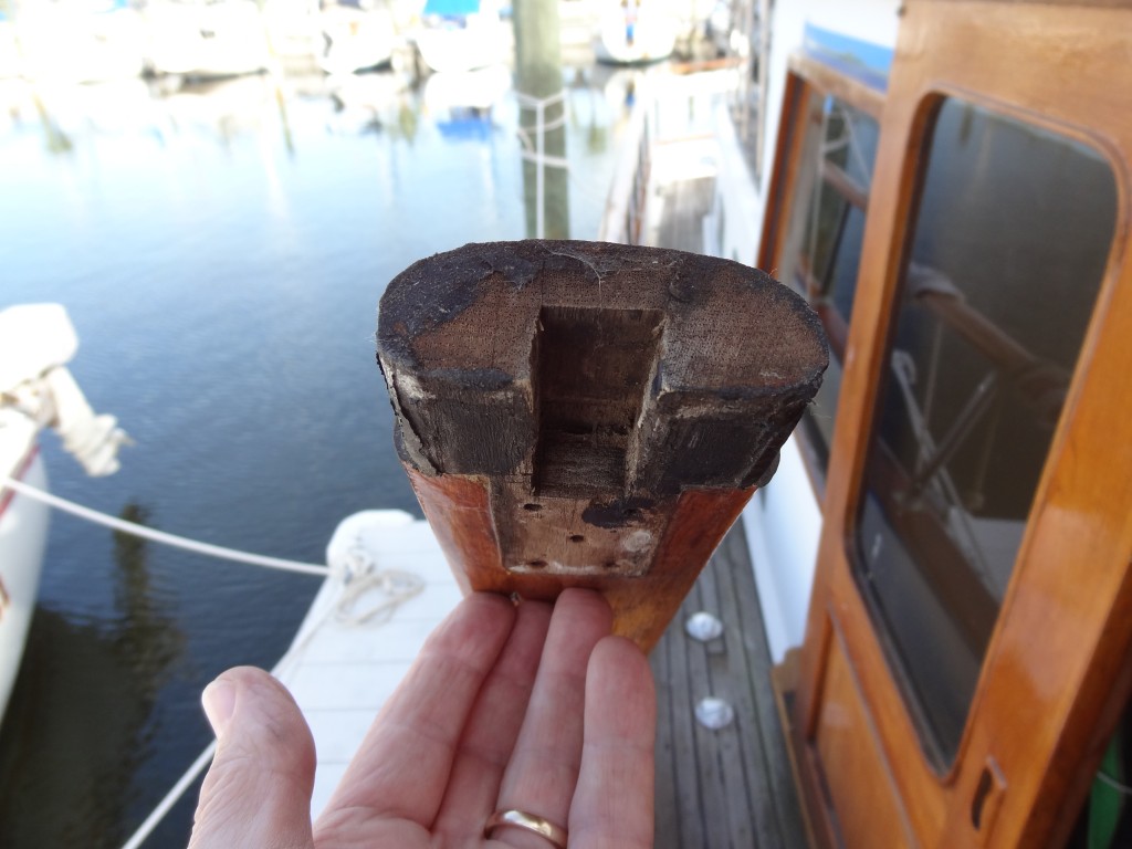
The third photo shows the end of the gate with the latch removed. You can see the hollow area where the spring box is located and how the teak has been slightly reduced to accommodate the thickness of the latch frame.

It seemed that a tack weld on either side of the spring box would be the ideal solution, but I couldn’t find any shop that would do the two tack welds for a reasonable price. Consequently, I used a “puddle” of JB Weld to fasten the spring box to the frame after smoothing out the two mating surfaces and removing the remnants of the original tack.

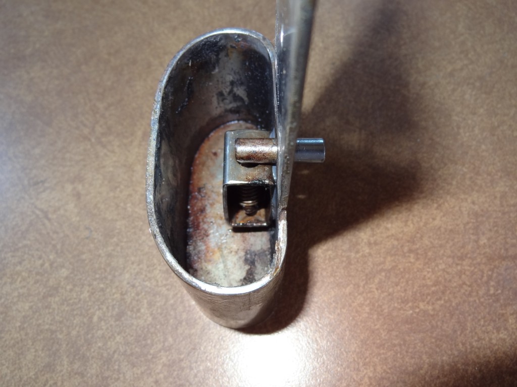
The fourth photo shows the latch back together with a bit of JB Weld showing around the edges of the spring box.

Hopefully, JB Weld will hold the two parts together; if not, I’ll write another article about how to get the parts welded together.

 

Project: Mast lowering/raising device

Our DeFever 41, Sanderling, has a teak mast (and boom) fastened in a tabernacle on the aft edge of the top deck. The mast with anchor light is 12 feet 9 inches in length and creates an air draft of 22 feet 3 inches above the waterline when the fuel and water tanks are about 1/2 full. The weight of the mast and boom together (135 pounds mid length) is such that it took two strong people to lower the mast and place it in the boom-crutch (doubles as a mast crutch when the mast is laid down). With the two of us cruising mostly by ourselves, it was a nearly impossible task to lower (and subsequently raise) the mast without asking for assistance. Our planned cruises into the Erie Canal and inland Canadian canals made it imperative that we be able to handle the task ourselves, and the only option was to create a block and tackle arrangement to provide the necessary mechanical advantage.

After consulting a number of other DeFever 41 owners, it became apparent that we had to come up with our own solution due to the full enclosure bimini around the upper deck, the weight of the mast, the location of a railing at the aft end of the upper deck, and my distrust of adding additional chain plates or pad-eye to bear the forces involved in lowering the mast with a block and tackle. The challenge was to create an attachment point for the block and tackle which would be as high as possible in order to minimize the loads involved as the mast went from a vertical to a horizontal position. The top of the bimini frame would not be anywhere near sufficient for the loads involved (and still have the bimini when we finished), and there was no other existing attachment point available. The only solution was to create an attachment point on a gin pole that would be up to the anticipated loads, removable, and stable.

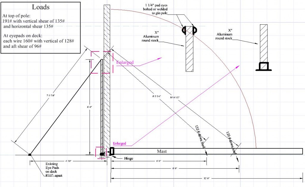
Here’s a side-view drawing of what we came up with. The mast loads of 135 and 120 pounds were measured using a digital scales with the mast in the horizontal position.

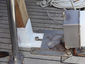
Photo 1 - Padeye and turnbuckle on deck behind bench seats port side

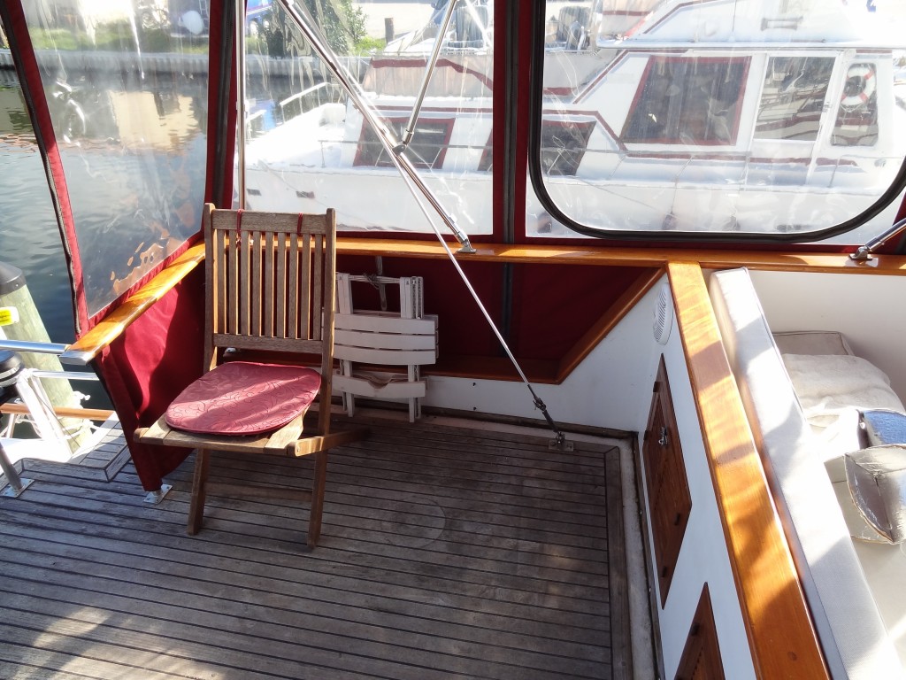
There are two existing pad-eyes with turnbuckles located on either side of the upper deck behind the fixed bench seats; these are normally attachment points for the mast’s forward stays. (See photo #1)

These are used to provide support for wires to the top of the gin pole.

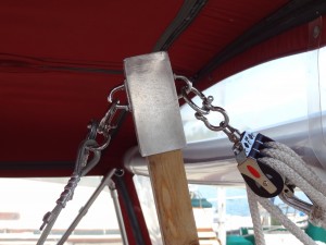
The interior dimensions of a preformed aluminum rectangular tube (provided by a friend) was almost exactly the dimension of a standard 2X4 wood stud, so instead of fabricating an aluminum gin pole, a 2X4 was used and 5 inches of one end were sanded down to fit the dimensions of the tube. A 5 inch section of the tube was cut from the stock and a plate welded across one end (a precaution that may not have been necessary). Two pad-eyes with rings were bolted to either side of the aluminum cap for attachment points. (See photo #2) Two lengths of galvanized wire-rope were cut to length and thimbles secured with wire clamps of appropriate size were added. The wire-ropes attach to the turnbuckles and to the gin pole with steel shackles.

Photo 2 - Aluminum gin pole cap with pad-eyes and rings

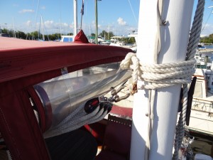
For the block and tackle we used two 3-sheave Harken 2.25 inch triple blocks with becket sized for 7/16” inch braided line rigged to disadvantage. The fixed block is attached to the top of the gin pole with a steel shackle; the traveling block is attached to the mast about mid-point with a steel shackle and a length of 1/2” line wrapped around the mast above a standard cleat attached to the aft side of the mast. (See photo 3) The fall is lead to the boat deck and is controlled from there. This allows one-person operation due to the great mechanical advantage and also allows the mast to be guided from side to side to properly lay into the crutch.

Photo 3 - Travel block attachment to mast

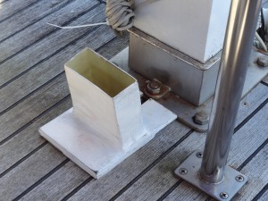
The base of the gin pole is inserted into a shoe made of fiberglass/epoxy to fit the outside dimensions of the 2X4 with a 1/2” base to fit under the nut and stud and recessed in part which helps secure the mast in an upright position in the tabernacle. (See photo 4) The base is inserted under the nut once the mast is tilted backwards slightly. (See photo 5) When the shoe was being made, several layers of paper and plastic sheet were wrapped around the end of the the 2X4 before wrapping the fiberglass in order to ensure the gin pole would easily slide in and out of the shoe to make storage and replacement easier.

Photo 4 - Shoe and tabernacle

Photo 5 - Shoe, gin pole in place and tabernacle with mast down

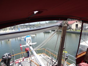
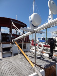
In use, the gin pole and supporting wires are assembled and the block-and-tackle tied to the mast; the forward mast stays are removed from the turnbuckle and the gin pole supporting wires are attached in their place; the base of the gin pole is located just forward of the mast tabernacle and the fixed block is attached. At this point the rig is fairly stable and will stand on its own. The pockets through which the forward stays pass in the bimini top are loosened to allow the stays to be pulled through (although they’re only pulled through when the mast is actually lowered). The nut on the tabernacle is removed and the mast tilted backward slightly with a slight amount of pull now transferred to the lowering rig. The gin pole shoe is inserted around the stud and the nut replaced and hand tightened onto the base of the shoe. The mast is then lowered a bit more until tension is placed on the rig; the operator then moves to the boat deck alongside the mast and coaxes the mast lower until the weight is held by the block-and-tackle and lowering is controlled by letting out the fall. The mast is guided into the crutch while the end of the boom lies on the deck. (See photos 6 & 7)

Photo 6 - Rig with mast down

Photo 7 - Mast laying in crutch

All materials were sized to exceed the anticipated loads by a factor of at least three.

The whole process takes about 10 minutes. Although raising and lowering the mast can be done by one person, a second person is extremely helpful in keeping everything steady and in pushing the mast backward to get the fall started. The whole rig stores in the lazarette.

Cruising the Erie Canal, the Canadian canals and through Lake Champlain into the Champlain Canal could not have been accomplished without the ability to raise and lower the mast easily. Removing the mast or permanently lowering it was not an option as we needed the ability to raise the mast once we were through the height-restricted areas in order to use the running and anchor lights and radar. This simple device made it all possible.

Project: Windlass replacement complete


This afternoon I finished with the windlass project, its wiring and reworked windlass/anchor platform. The anchor rollers and anchors (one Danforth and one SuperMax) are now in place, as well as a Lewmar chain stopper (at the top of the small platform just forward of the windlass). The top of the platform is also covered with 1/2″ starboard for protection from dings and scratches.

The engine’s injectors have also been removed, rebuilt and replaced over the past several weeks.

Judy has a few days off later in the week, so we’re going to take Sanderling out and practice anchoring with the new windlass, test some of the systems, and generally see what needs to be accomplished before we leave for the Chesapeake at the end of the month.